there are loads of guides to building retro pi machines. but this is a slightly different build as going to use 1TB SSD image so will be running an SSD drive on a pi 4 B
So why am I doing this well I was going to put together a retro flag GBI 2 but as raspberry pi modules are limited supply here in the UK/World Wide I decided as I had a pi4 B gathering dust I would review a different case that supports SSD drive.
I have been wanting to build something that I can let my son play with as he is a little young for the ps5 or the VR headset. I was looking at desktop cases and then found argon one v2 with USB SSD support.
A little bit of an update will be building a reviewing a GPI 2 in September as have managed to buy one in Germany and ship it to a hotel I will be staying in so I can get around being outside the European Union. 2022 issues I hate that we left not going to get political.
So what you will need to build this
Raspberry Pi 4 Modle B.
Small micro sd card.
1TB SSD drive.
Argon one v2.
USB adapter for SSD drive.
pihut argon one adapter for SSD 2.5 drive.
game controller Xbox pc controller I had kicking around
Burning the image:
Now for the fun bit, I tried this process with the 1TB image and the imager took around 8hrs it didn’t like it so instead I’m using etcher software to create the SSD image I have the drive in a quick swap 2.5 enclosure USB C so loaded the .img file into etcher and hit write
Bear in mind this is going to take a long time to burn at least 3hrs once it’s done we are ready to build the system.
Didn’t work again argh so after joining rick dangerous discord group and chatting with him and some of the great users I found 2 issues one I had a bad drive enclosure not compatible with raspberry pi. 2 the retro flag enclosure I had originally brought didn’t want to work so I sent it back and off the group recommendation I brought an argon one v2 and USB drive housing for it off pi Hut. that turned up surprisingly quick. Rick’s discord link below and his youtube channel.
I also learnt from rick about the about-to-be-released version of his drive the [1tb]-Rick.Dangerous.Insanium.Edition.RPi4. Over 60 systems and 8,400 games on board and growing with user input.
A week later it launched and I downloaded it off Usenet 3hrs 30 with the new version I then imaged to a SSD drive from an old project that I had kicking around the workshop. it ready to use. more information can be found on the link below.
this isn’t too complex you will need to put the heat sync tape on the 2 chips mentioned in the documentation. once they are done place the pi into the enclosure at this point you will need to plug the sideboard into the audio and HDMI ports and power then insert the pi into the gpio pins will post some stock images below. 7 screws and it built
Plugged in the power and turned it on wow Rick’s image is awesome some screenshots are below and it’s continuing to grow. this is on my 65″ 4kv and there are a lot of systems from my childhood. I will be having a retro night soon.
I will be doing a full review of the drive shortly once I get back from holiday and work commitments
ricks also going to develop a hand-held version for the GPI 2 I will be coming on the journey shortly with the discord team.
this has been a bigger build than I first expected around 100 hrs of printing a lot of remixing was involved so some things worked some things I have had to print again and again till correct. think they are all correct now as they fit for me.
As will any project files they are a work in progress. still need to reprint final fixes to test but the current design work with some drilling or being an angel so no rush for me. i would say there are a good few days of printing involved with this project. but well worth it.
So what this part covers:
All in one Cr-10 Remixed for Dual Y-Axis linear rails kit
UPS 12v big tree tech
Filament runout sensor big tree tech
Modifing TFT screen firmware.
Dragon Hotend and issue correction
BISQU Flexplate
All in one Cr-10 Remixed for Dual Y-Axis linear rails kit
This is a remix of this design by Cornely_Cool can find the original design here. you will need these files for some of the builds my remix replaces the front-rear panels front left panel and several of the base plate files. this is a work in progress it works for me as of me writing this blog post.
So why am I doing this the original printed mod I built-in part 3 or 4 doesn’t work with the upgraded linear rails so It doesn’t fit so going to make something using an existing design with a remixed twist as its not 100 % right for me due to the dual linear rails and the design wasn’t using SSR and some other bits. First up going to salvage parts and order up some metal work going to raise the machine 60mm and have another 70 hrs of printing ahead of me first up parts. needed some aluminium 2020 and 2040 some connectors to hold it all together some corner plates and some new rubber feet as I disposed of my original feet from my cr10 also have hight clearance is an issue with a shed roof. might still need to lower racking. have also ordered a small 5v 3amp PSU to internally power the pi that’s running the printer. as this is a custom build have also ordered some aviation plugs to tidy up the wiring and install better-suited wiring. I will have a sonsoff switch as master power on and off and use relays to turn on and off power and lights for web camera. I will publish a full shopping list. end of the post when I have calculated what I used and what you will need. will add build of material
Time to start the remix so starting with the base panels going to remix the Mosfet panel as don’t use one as running a silicon heat bed. so will house SSR relay, a 2 channel 5v relay for lights and printer and UPS board if and when it all shows up.
this is done using the panel as a reference and using PCB footprint diagrams have added a 6mm standoff for each part.
will house SSR UPS and 2 channel 5v relay it a work in progress relay fits just only screws fit
Next up I am going to remix the raspberry pi and pi PSU plate as I am going to use a hard-wired PSU 5v 3A so will need to make some mount holes for the PSU but first going to test its powerful enough. as I don’t have a reference diagram going to photograph the underside of the PSU and measure it using it as a reference image. will then trace holes for mount. won’t print it till I have tested PSU. have made some air vents and bars so i can make holes to mount it when it’s done.
the PSU holes are off as on the wrong side but will drill and bolt PSU in place. The final file changed but might be off.
The final modification is to the mainboard fixing plate so used the existing plate as a reference for size then added footprint overlay to trace holes for mounts.
insterted image of board set to size as reffrenceadded standoffs on over layexstruded finlal plate for prinnting
the final hurdle was going to print the massive PSU plate on the cave monster cr-10 but due to wiring snagging I cannot print on it so into Prusa slicer have cut it in 2 will print half and half on both the Prusa so I can do it in half the time will line up and glue the halves together.
love the cut functionas i have the print farm up and running i will print half one both the printers so saving time.
Now that I have remixed all required base plates now I am going to centre the middle post I have remixed the font panels to be blank as due to the dual linear kit I cannot fit a front-mounted screen. so going to remake the panels to smaller and more central with a 5mm notch to allow for fixing plates.
Gone for a central notch 5mm deep changed it again since this maid it longer.
Next, up is the power plug panel got to notch this and move the power connector as it’s right in the way of the plate.
slotted for brackets with 5 mm and move power connector by 20mm to the right changed it again as just on the borderline.slotted by 5mm ready to print.The last plate finishes just base plated to finalise. just had to add a hole for cables for the screen
The last panel was modified for screen cables for mounting to the frame.
Time to start printing I am going to run it all in PETG. time for some overnight parts I am going to set my Prusa’s going shame I haven’t reinstalled Octofarm to run this but will do on the next build as will be running 3 printers in it. About 4 days in now all printed apart from pi and PSU mount that’s currently running and some fixing brackets. time to build the base has been tweaked the construction of the metalwork with some extra brackets to make sure this going to the stable with the printer on top of it.
last part on the prusa printing then to assemble it all.
Oh wait fan director last 8hr print that’s overnight parts for as I am already deep in assembly.
last print of base builds overnight parts.
Time to build it.
Time to put it all together for the final time hopefully and I can then put a pin on this machine.
first up assembled outer frame with base runners and corner plates with the feet i have brought. will bolt down the centre rail once I have centred it on the base plates.
metal works arreved atime to start putting togethercenter rail in time to bolt it togetherand im out of 10mm blots damit.
now I have a squared base I will add the uprights and bolt them down with the L brackets i have sanded the tabs on the printed walls so starting from 2040 I placed the first part I then added a bit of 2020 in the middle and continued on till all the walls was installed then using 2040 plates i bolted the base to the 2020 uprights. I will add another bracket on top of this to secure the printer to the base.
First panel is in. all the walls are fitted.
now on to the base panels, I will place them loose before I add the fixing clips in place.
fr dry fitting panels.all fits well.not 100% lining but will workjust going to change pi panel as psu wont let me fit the power connecot to pi.
all my components line up perfectly well almost but still bolts down sold just need to adjust the centres slightly as the footprint diagram I found is wrong on the relay. I am getting better with each project build. now everything is in place have added the clips have bolted down all the components apart from PSU as need to modify it for the upgraded fan.
fitted new PSU base plate but holes are off, needs to modify
Final version the pi & PSU plate is done holes are wrong but I just drilled new ones and screwed it down with some 6mm M3 bolts I will start wiring up tonight.
actually going to need cable management. so time to fire up the Prusa 1 more time for a plate of connectors.
the last print for the base.
The wiring
First up will run the mains wiring from the 3 pin kettle connector to the Sonoff switch then across the on/off switch for the pi PSU and the main printer PSU. now I have the main power in.
Main power all in forgotten my wifi password so I cannot test the Sonoff all fit perfectly.
Next, I will run negative connections for the 2 channel relay and link the relay to the pi so I can control it via Octoprint. I will then run the positive to the PSU and lights circuit for the web camera. next up are the jumpers from relay to the raspberry pi going to use 5v ground gpio 23 and 24 pins I am also going to use 3.3v and pin 9 ground and pin 14 for a temperature sensor inside the enclosure so I can adjust the fan if it gets too hot inside.
Ok, my worries about the mini PSU and voltage is fine there is no under-voltage which is great as sometimes things are not what they are advertised as.
time to pull out the wiring diagram for the mainboard.
list all connectors as you can see negative and positives are needed on end-stops and thermostats if not get kill alarm so on the end-stops and thermostats square is= to ground.
end stops and motor connecotrs are wired board side got to do some soldering but will cover that later as need to make some new wires for the heat bed and y-axis.
I am actually going to modify one of the front panels to house a Micro sd card reader and a fan speed controller PCB so back into fusion 360 going to add foot block and add 2 3mm holes to mount the front 2 PCB holes as then in the main plate I will add an 8mm hole for the potentiometer. then over the other side of the panel, I am going to cut a hole for the sd card reader to squeeze into I will then fix it with hot glue. as the original design used a USB switch to allow for firmware update the skr board only allows for MicroSD upgrade so as the board is going to be embedded this will allow for firmware upgrades in the future.. this will be a 4 hr print I think. as I test fitted the 2 halves I needed to reprint this anyway as it’s off by 10mm so now will fit perfectly under the front plate support
So out with the callipers, I go to make everything will fit and is sized correctly. time to modify the sketch.
will do an overnight prototype print. well, morning has come and yes everything fits fine just need to screw the PCB down and hot glue the sd card extension in place and we are a bit of sanding for the tabs and should be good to fit. note to self make sure you sand the tabs another 3 hrs print and will defently resand the front panel as snapped a tab these things happen when prototyping but its starting to take shape.
whilst I’m at it going to add 10mm space on the rear power panel as it was very tight prefer there is some wiggle space more airflow as well going print it on ultraviolet tonight back on with the assembly tomorrow.
redesigned as was too tight on the centre spacers.
All panels are now fitted going to cut myself an aviation plug holder jig. so out with a sheet of acrylic time to cut and bolt together.
So over to light burn a sheet of acrylic in the machine let make this design I got off Thingiverse https://www.thingiverse.com/thing:4201220. I have relayed it out slightly different as I want to fit on a sheet of 300×400. if someone wants it will share it.
as I want a good connection going to start with the 4 pins i have given up on the six-pin as NEMA wiring is too fragile.
ready to cut.
Not everything you find on Thingiverse is right so had to modify the file slightly to get it to work but now a more compact jig. as the dfx is segmented and didn’t cut right in light burn fixed now and modified the base as was too big for smaller workspace ready to solder tonight. got 1 socket to solder
assembled ready to make my new connectors
Nice and neet now for the heat bed connector need a new connection as the board is about 20cm further than it was originally also my bad soldering means it intermittently doesn’t work. so time for a fresh connector.
time to solder up a new heat bed connector with longer wires so I can wire direct to PSU and solid-state. out with my soldering iron I know the following
Pin 1 = Thermostat Positive if wired wrong alarm will sound on SKR board
Pin 2 = Thermostat Negative if wired wrong alarm will sound on SKR board.
Pin 3 = Heated Bed as 220vac voltage don’t matter which goes to witch
Pin 4 = Heated Bed as 220vac voltage don’t matter which goes to witch
2 down 2 to goready to instll
have put continuity meter across the pin and end of the cable and they all check fine
now to wire it all up and we should be good to test.
all ready just need to shorten the neo pixel cable as made it way too long. going to use the bit I chopped the neo pixel wire I will use for the filament run-out sensor cable. Then it’s time to finesse the cable management.
The next issue the fan direction vent is hitting the y axis so going to make my own custom offering so going to find the footprint of 120mm fans going to make it easier to fit low profile fan shrowd. should have space as gone for 35mm high to 19mm high
So should have good clearance space. 6hr print will run tonight need to swap filament as running low on Neon orange.
Done just need to see if it fitssd and fan controler fittedrear shot of it all.just isnt sitting right.new Fan air directonal. nice and compact but does buffer the air might modifiy it more in the future,
The wiring list is getting shorter just time consuming getting there.
end stop and motors temperature sensors and relay wiring left before I’m done.
Time to link the raspberry pi to the relay using 5v ground and pins gpio pins 23 and 24.
Temperature sensor installs time so using 3.3v ground and Gpio pin 14 for the probe have added the Dupont connectors to go over the gpio pins going to have to do some changes via rasp-config to let the system know pin 14 is sensor pin. but will check if this is needed or not as it is an old guide I read. I will also need to add a plugin so it will display the internal temperature of the enclosure so I can monitor and adjust the fan speed accordingly.
going to have to change the sensor type as this type I have installed does not have a pull-up resistor on it so just ordered another type off eBay so will swap it out.
Temprarture sensor installedJumped to the raspberry
Finally, The wiring is now all complete just need to test everything works.
finished all internal wires oh wait missed the lighting circuit Relay.
The camera light relay I have pre-made a cable from the 12v supply the positive will go to the power connector negative will go via the relay so I can switch camera lights on and off when a print starts and ends. have had a change in the design as I’m not using USB switch going to wire power connector to where the switch was going an install an A to A USB panel mount so I can connect the camera to pi externally power will be via the relay so I can turn halo on and off if required, should have parts Monday. as I wired the power socket tonight I had a thought about the USB connection wouldn’t work. back over to fusion 360
power for light rig is in.
Designed the first version it’s printing now but it’s not going to work as needs relief for the screws so have remixed it further and come up with this going to print it so have both options but think this is the winner.
v2 think this is the winner
As you can see from original to remix v1 and final v2 these are the things you have to take into account when remixing a project.
orignial version 1 and 2
In fact, I am going to redesign it again as the cable layout is different so back into fusion I go doing a scrapy print to see if it works but this should be the final design have made a few changes including screw head relife and it fits perfectly added to the remix pack
version 3 with cut out for plug that turned up
this project is pushing my design skill and I love it.
the finished item I do love playing around in 3D print.
Time to fit it all into the machine.
fitted like a gloveall wired in
Right, I am on the home straight I need to make some form of protection for the printer’s innards.
going to cut some black acrylic insert them in the middle of 2020 extrusion as dust covers.
so been thinking about how to do this without having to remove the front of the printer going to do some testing. I am going to cut some test bits 20 x 74 mm at a start to see if I can insert it then centre and add a fixing clip to hold it in place I will then make will also design a middle clip that can be removed to gain access. well,
that’s the idea, time to make some test bits. so over to light burn and as I have some offcut left from the jig build going to cut some strips to see what can be inserted,
time to cut some interest to test have labelled them for ease of use
So looking front on Left = 77 middle = 146 right = 75 now to make 2 x 200 long size X plates for each area will then 3D print the customizable design for centre plates then to design some clips that will be after I have the covers fitted.
I have decided to make it a 3d printable version obviously they will be subject to where your cross braces are. but you can customise them in the slicer. i am going to print my covers so they match the base as I could cheat but I want this to be a mostly printable design. also, put a clip together
the first plate is printing
here is the centre plate design will be making left 70mm, 138mm and right 68mm. the centre area 72mm across. total area 100mmFirst panel inone side done.
Clip design I have put these in to hold the panels in 3 per panel so 24 in total. currently printing a sheet.
final plates are printing on the printers should have all the dust covers done tonight then I am ready to assemble the 2 parts have hit one minor snag as the end stop bar is skimming the middle plate need to take a few mm off it to get it to work right will think about how I do this might just be a shorter screw and a 10mm off the tube with a hacksaw. No, I own a 3d printer. so now printing a shorter 11mm x 20mm tube and have a shorter screw to fix the issue.
only issue is the centre plate as the end stop bar is clipping it.
All fixed worked like a charm now does not rub on plates and makes contact with the endstop. all plates fitted made a cut out for dust cover so waring was more neat.
Dry fit works well.
dust covers all fitted and wiring from neo pixel hidden also hidden the filament sensor wiring if there’s any interest will publish all the other bits I found on Thingiverse that used to help with the project.
Yay parts from china
Just as I was about to put a pin in this build and post the post I have now received parts from aliexpress so back on to some more upgrades. lol so this will be tomorrow as one PCB to fit and wire and one sensor to attach. and a Flexi plate to stick and fit.
So a new day has dawn going to try wrapping this up today bar printing or tuning.
UPS big tree tech
This should be easy to install one 3 pin plug to the mainboard from the ups and 12v supply just got to figure out where to place the board in the enclosure I think I am going to make some holes and add some standoffs as I did with the 2 channel relay. need to look into firmware changes for its use will cover this at the end of this post.
My fingers are crossed my calculation for the footprint of the board is correct and this just pops in with some m3 screws. Well, I’m too good fits perfectly just got to finish wiring it up.
Make sure that the + & – are wired correctly as will destroy the PCB if wrong they are labelled on the bottom of the PCB then links them to the power input on the mainboard like shown below.
then insert the 3 pin connector and connect to pwr-det on the mainboard and then back to ups PCB and it’s all installed hardware-wise.
Now for firmware changes
There are 2 files you will need to change first is in the feature folder look for powerloss.h
I have changed debut and saved each cmd this will save the last state on the printer if there is a loss of power now over to the Configuration_adv.h search for POWER_LOSS
then uncomment the above this is set up for my printer mainboard so pin number might need changing on your device. and purge and retract might need changing as well.
will compile this after making other changes for the filament runout sensor
Filament runout sensor big tree tech
As I waiting for this to arrive seller sending another one middle of February so instead of moping around the workshop getting ready for it all to arrive.
Ok have found a bracket on Thingiverse I am going to remix it so I can mount the bracket directly to my 2020 so will be adding 2 tabs in Fusion 360 so I make this a reality. first, I am going to import the mesh in and will draw two rectangles using the top face of the bracket I then extruded them by 4.40mm then made a centerline in a sketch and added matching holes time to print
Quick and dirty modification but will work.
I will print it shortly the spikes will print not sure why they ended up there are joys of modifying a mesh
Just waiting on the current print to finish should relay run the farm but need to get neon orange up and running it’s on my list of things to do. it’s a long list as always.
Printed ready to fit when I get the parts. just test fitted will just what I wanted.
works on 2020 fine.
As I now have the parts time to fit it all to the frame for real as the sensor has arrived.
hidden all the wiring in the frame with some clips.
Going to connect it to the mainboard E0-STOP port you will have to switch it on in the firmware pin 15 was already selected for filament runout.
Now you will need to turn it on in firmware so in configutation.h
find the following FILAMENT_RUNOUT_SENSOR and uncomment it like below.
Next, scroll down and uncomment the following FILAMENT_MOTION_SENSOR and FILAMENT_RUNOUT_DISTNCE_MM set it to 7
and with that just need to reflash with v5 of the mancave monster firmware on the mainboard and we should be good to go.
My Current Firmware CR-10 BTT E3 mini 2.0 with BTT UPS, BTT Filament runout sensor, BL touch and Neo Pixel 18 pixels installed compiled here if you want the vs code files ask and will happily link it for you.
all components are now installed going to join the 2 printer halves and running initial tests. fingers crossed before I permanently bolt them together. Wiring issue, not a big one negative on neo pixel is the wrong way around not a biggie just taken a photo of the pins.
Mine was the wrong way around so out with crimp tools and time to make it right.
remade the connection so let’s test it again. now seems to all be working.
Homes check bl touch works check hot end heats not working for heat bed erm ok not heating need to check the wiring.
Got a feeling negative is what I meant to pass through the SSR going to go back through my notes.
Was 2 issues had heat bed plugged into the extruder and hot end in the bed and the negative was positive no damage all fires up now and works
Just print the front left panel with a modified hole for screen cables. so going to leave that running overnight, just fitted and perfect so that’s finalised.
One thing i will need to revisit is the relay board but I think that will be done in the future as projects are already way overrun and used lots of PETG I really need to invest in centre callipers they are uber expensive one day shall order some.
Time to modifiy my racking
The next job is lowering the racking so I can fit the new printer on the shelf need to move the spool holders down and then drop the shelf level down by 15 cm approx.
cleared the shelf and now to focus on removing shelf and old wiring as will rehouse the wall-mounted pi down also binning cheep fans as they temperature should never get that great and the nose one of them I producing is bad.
spool too lowspool not high enoughJust rigjht
Have managed to drop shelf approx 120 mm have refitted shelf and refitted Prusa’s have moved my pi off the wall and disconnected fan. I shall monitor CPU temp via the plugin.
space is ready for the new printer
Now to place the printer in its place well nearly first flash the firmware and cave monster ready for action well nearly as I want to finish off the mods before I set it in place.
TFT Screen firmware configuration
One final tweak I wanna look at is the firmware for the screen as want to disable a few features and rename some descriptions if I can not sure it’s possible. but by the power of google.
first up looking at the config.ini
In order for the TFT, firmware is able to provide all of its functionalities/features, ensure that the following options are enabled in Marlin firmware.
General options:
EEPROM_SETTINGS (in Configuration.h)
BABYSTEPPING (in Configuration_adv.h)
AUTO_REPORT_TEMPERATURES (in Configuration_adv.h)
AUTO_REPORT_POSITION (in Configuration_adv.h)
M115_GEOMETRY_REPORT (in Configuration_adv.h)
M114_DETAIL (in Configuration_adv.h)
REPORT_FAN_CHANGE (in Configuration_adv.h)
Options to support printing from onboard SD:
SDSUPPORT (in Configuration.h)
LONG_FILENAME_HOST_SUPPORT (in Configuration_adv.h)
AUTO_REPORT_SD_STATUS (in Configuration_adv.h)
SDCARD_CONNECTION ONBOARD (in Configuration_adv.h)
Options to support dialogue with host:
EMERGENCY_PARSER (in Configuration_adv.h)
SERIAL_FLOAT_PRECISION 4 (in Configuration_adv.h)
HOST_ACTION_COMMANDS (in Configuration_adv.h)
HOST_PROMPT_SUPPORT (in Configuration_adv.h)
Options to support M600 with host & (Un)Load menu:
Options to support dialogue with the host (as a prerequisite)
NOZZLE_PARK_FEATURE (in Configuration.h)
ADVANCED_PAUSE_FEATURE (in Configuration_adv.h)
PARK_HEAD_ON_PAUSE (in Configuration_adv.h)
FILAMENT_LOAD_UNLOAD_GCODES (in Configuration_adv.h)
Options to fully support the Bed Leveling menu:
Z_MIN_PROBE_REPEATABILITY_TEST (in Configuration.h)
G26_MESH_VALIDATION (in Configuration.h)
I didn’t use this as couldn’t get to compile I will revisit this
Z_STEPPER_AUTO_ALIGN (in Configuration_adv.h)
so that’s the merlin firmware now done not to look at the config.ini.
custom logo
cave monster
so lots of settings and functions here have changed a handful of colours and the way it talks to octoprint.
next up going to look at the actual firmware pre-compiled so I can see what changes can be made. that will be a separate blog post I have added a new icon set and flashed the screen with new firmware to see if it helps.
Dragon Hotend and issue correction
K decided I would go the full whole hog and upgrade the hot end as well. as I wanna look at the movement in the x carriage on the extruder bracket. I also why it is quite tight on the belt.
Issue 1
I fixed it was the hole the direct-drive bracket is bigger than the m5 to linear rail bolt hole so have used 2 countersunk screws to centre the bracket. works well,
Issue 1 FixedNew hot end fittedexstruder reassembeled
Fitted the dragon
I have removed the old OEM hot end. 2 screws and that’s gone now to fit the dragon hot end using Capricorn petg tube between it and the direct drive all fitted now to put the hot end back together upgrade is done. but not quite right cannot get filament into hot end tubes not quite long enough so time to order a length of it so I can get this right.
Issue 2
I noticed there is a lot of friction on the belt so I am going to swap the pully end around as I want this to be smooth and can align the pully across the beam. 4 front screws removed. pully off and rotated now to put the machine back together much smoother think I have fixed it might need a slight tweak but let home the machine and see what happens.
just going to make a benchy test. before I fit the new flexplate.
running into issues with filament sensor the hot end now clogged got a feeling the Capricorn tubes melted so I am going to strip down the hot end tonight and have a look and see if it’s down to that as removed nozzle and still cannot get the filament to come through. have ordered a back up hot end the big tree tech v6 hot end and a fixing bracket as a backup as got a feeling this isn’t right.
will disable the runout sensor for the calibration as I have a feeling it’s thinking it’s a clog on the hot end even though there is now a clog.
removed hot and cleaned and the issue blockage in the tube put it back together loaded it ran 20mm through it and bam blocked again so might be my filaments shit or the tolerances of the tube is too tight might try a different batch and see if I get any joy other wire going to revert back to my back up but that’s going to delay first print. by 3 weeks but going to launch this part of the build and then come back when it’s all printing right. at least makes me know that the runout sensor working. so will re-enable it after I have a calibrated machine.
going to first install the flex plate whilst i figure this out.
BISQU Flexplate
This is something I love on my Prusa printers will hopefully be the same experience. so to install going to need to stick the magnetic sticker to the glass bed.
so have turned over the glass sheet and cleaned it using isopropyl now to apply the sticker sheet went down will not be 100% straight but no one will notice.
Time to cleanSticker fittedAll installedAnother anglejust need a working hotend and good to test
before I test the plate on top. going start by resetting the EEPROM and then going through calibration again as don’t want to mess the sheet up. but that will be in part 7
all fitted now a waiting game for the new hot end so will leave this here final part will be testing it all out.
A happy New year to you all, Incoming parts have arrived so time to finish off this project last 6 upgrades firmware recompile and hopefully will be all done.
Yay The kit arrived when I was away so a bag of bolts and t-nuts aluminium end plates and base plates.
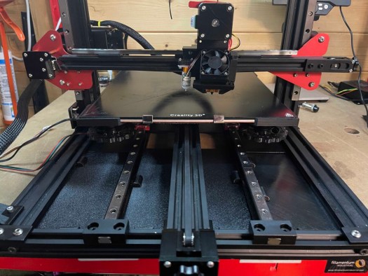
this is going to evolve some guesswork as with all china kits they never provide any instructions but basically will fit the 2 cross braces and add the rails to both and bolt them down will leave the supports lose so I can make sure all is plumb and attached the bed this is in theory fingers crossed.
Wow, they are tight going to loosen the frame ok now to centre them as best as I can. Now that I have the 2 cross members installed loosely to add the linear rails and 18 nuts and bolts on each rail to bolt them down lining them on the cross brace.
Now to mount the bed to the rails start with one side front bottom placing aluminium spacer and 30mm bot I fix in place I can see the left is off so nudge them to line up so I can put a bolt now to install the remaining 14 spacers and nuts. bed or carriage is attached I check it for lateral movement nice and smooth so I reattach the belts and repeat can that the top needs to come over. now I have it centred time to tighten everything up oh then looked at reference images of add noticed as i had 3 bits left that i couldn’t identify.
They are to make contact with the end stop. so add them now to install the rail end plates so another 8 screws and t-nuts. 4 aluminium covers later it’s done
Now waiting on spacers for the bed as I manage to lose once so should have them Friday also chatting with the vendor as my big tree tech package has gone missing in my absence. below is a montage of what happened through the build.
Lets get startedfixing platelinear rails.bot cross sextions fitted18 t-nuts per rail yay menow to the other side.all bolted down now to fit the bed10 spacer and bolts installed 6 to go.can see the belt is off time to nudge it.nice and straight added end stops
Neopixel install
Bit of 3d printing have found a led tape mount that I have modified to fit the gantry perfectly I am currently printing the bars in 2 parts will then print the end caps. 3 hrs later will just do a test fit tonight. ok, the first attempt failed so going to print into parts and have gone for a solid infill to reduce the movements see how it turns out. the bit that did print fitted though.
failed again argh going to look at slowing the print down to see if I can get it to complete
attempt number 3 with a raft this time let’s see if these thin columns will print.
So added a raft fingers crossed. Update 50% done still holding.
I miss calculated the length going to use a failure so sort it so chopping down a failure bit. also need to get a heat gun on it to take away the stringing.
made a mall 30mm section out failed parts and put 12v thought it to see if it lights and it did now to finish the cable.
lights up now to finish the cable.
right, this is going to be a bit of guesswork I will need to see how it pans out as I have changed my mind on how I am going to set it up but from what I can see I will need a 1000u competitor and 330k ohm resistor the competitor will go between ground and live and the resistor will go in line with data wire. I will make a 3 pin JST Xh connector so I can plug it into the mainboard this is the simple part. to install it I am going to stick the 18 LEDs to the top bar of the printer and stick it the v slot or I might stick it to some insert clips I have found that will allow me to stick it to it. still toying with this as I type this post. now the firmware is where I am going to start asking more questions as no one seems to be able to answer my questions. argh, have contacted support as they all seem to be for an earlier version of marlin firmware see what they come back with.
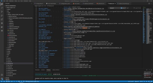
Figured I all out myself and was it a fucker so bugfix changes layout you will need to go ini folder in vs code fetures.ini and then change the following. go to adafruit comment on neopixle_led change to the following. NEOPIXEL_LED = https://github.com/CommandoreBombardiero/Adafruit_NeoPixel as shown below.
Now go configuration.h and search NEOPIXEL then change like below.
corrected code
Then build it will fail with something about the delay so then go find Adafuit_neopixle@src- some numbers and letters you will need to change the location in the brackets to the location of your delay.h file in marlin/hal/shared/delay.h can see it for my dropbox location below.
build it again might fail but then if you build one more time success, wow my mind is numb now only taken the best part of 3 weeks on and off to get this to compile now to make and add connectors and hopefully, it works.
Next, up now I have it compiling is to make up a 3 pin plug so looking at pinout i know i will need a 3 pin JST connector and 3 crimps and JST crimping tool this is fiddly could also be done with Dupont connectors if you didn’t have JST ones kicking around.
Time to update the firmware wish me luck. sd card in hand. a bit nervous lol.
hmm, not working I am not sure if it’s the wire or something else going to check through my notes and see if it’s something like the wrong controller pin or it’s tested the wiring and got a continuity check on negative and positive.
checked over the firmware code and had assigned the driver pin as 4 instead of PA8 will flash the firmware again v4 I change the version number each time I make changes to the code.
yay it workedback in the holdercable managment clips work well.
Now to put every thing back together and add some cable managment an figure out a way to mount the unit to botom of the printer well untill i figure out my next mod more on that in part 6. will also need to re calibrate the first layer again hoping for the last time.
Once dialed in going to start running parts for the next modifcation going to take a few weeks to get bits in from china and ooznest also got to rework some bits as well. going to do the rework first before spending out on parts. as all these mods hav spireled out of control.
Next steps
When the bits turn up from china I need to enable filament runout sensor and power loss in the firmware but that’s a lot more strait forward.
Will make changes to config.ini for the screen when get the new bits as will allow the main board and Octoprint to communicate with filament runout sensor as that’s where its plugged in.
We’ll all short lived control box don’t fit under machine to going to make something better see part 6
Ok, what’s so hard about adding a keyboard drawn to a desk well if my desk was solid wood would not be a be an issue but seeing as I cannot afford a nice metal or wooden workbench I have gone down the 1200 x 600 racking route. and have had to balance my keyboard on shelves under the desk no so easy when the bench is full.
The Idea
had been bugging me this for some time I was going to make my own draw using some wood and draw runners. but then was thinking back to my days in IT when we had a massive server cabinet with keyboard draws. so straight on to amazon. found 3 or 4 possibles but none had the right mounts or size for the keyboard I am using.
I then found laptop draws and that was the answer to my issues. prime delivery next day now to make this fit. been running ideas in my head since yesterday on how to fit it as fits the 50mm gap I have created.
The Draw
Fits very nicly
What it will look like
The plan
I am going to cut down 1.8 meters 50×47 mm wood into 600mm lengths 3 of them.
I will then measure and drill holes fro draw mounting points through the wood I will countersink them so I can add bolts flat to lengths will then blot them to the 2 lengths.
the 3rd length I will use to strengthen up the end of the bench will be making a quick release for the table saw, pillar drill and sander. more on that in another project.
I will now measure up the tabletop and drill 3 holes and countersink them into the tabletop will then screw down the tabletop after that is complete I plan to use carpet tape to hold down the cutting mat. well that’s the plan wish me luck
The build
Monday Night:
Hand saw out 3 legs cut. time to test fit them. ok, Need to take 5 mm off each length as slightly too long going to notch out the top and bottom so it fits in the frame. Have one done works just need to set up the piller drill as want my holes to be true then will test fit
One in 2 to cut and notch
giong to add a usb hub to the back of tray
Noctchs done fits nice and leval
I want them sitting nicely in the frame as screws from above will clamp them down onto the tabletop. hold on now waiting on bolts as I could not find any locally so amazon delivery tomorrow. will notch other 2 lenghts tommorow.
Tuesday Night:
Time to replicate the frist length 2 more times and fit every one more time before i put the top back on.
1 done 2 to go
Time for a scketch for idea
All leval and notched
Now to measure drill and countersink. fits like a glove now drill the tabletop. on a roll now to stick cutting mat down as this project done.
When you know how to make 3d models and prototypes 3d printer is one of your biggest assets in the small workshop. this whole project took 4hrs 30mins to complete from idea to finished working design and 4hrs of this was the print time.
Back story
As I am currently waiting for virgin media to fix an issue with my router before I can make the new website live as need to port forward from the VR machine. So to make sure i can just start to work on projects I am re-laying out the workshop. I have had tools sticking out of dump bins as I didn’t have a space to place them it’s got a little out of control. so back to the problem at hand and the point of this post.
The issue
Bocsh Wireless glue gun never found a handy spot for it. so last night after pulling out my callipers for some ruff measurements. I decided to make a handy wall mount.
The MountDesign
So fired up fusion made a 40mm circle and extruded it to 55mm then added a new sketch and made a new circle 35mm at on end of the cylinder I then cut into the cylinder 30mm I then added a 5mm hole through the middle and then using a bevel tool made a cone to exit.
I then flipped the design on its side and made a 55mm x 30mm rectangle I then moved it from the central axis to the outer edge of the design and extruded it by 5mm I then added 2 countersunk holes. by using a circle tool and the bevel tool. Now to export it to print.
Now to drag it into Prusa slicer and slice away made this design so won’t require any supports of rafts to print. printed with 25% infill. gcode ready for upload to octoprint. Away we go overnight parts was a 4hr print left it going as having rigged up relays for the lights and power of my printers so once completed it will shut off.
The next morning– The result
As you can see worked flawlessly apart from me being overzealous with my talk driver screwing it to the wall. but it’s perfect for my requirement.
My next job is to add a keyboard draw to my workbench using the track system but need to go grab some bolts and 50mm x 50mm wood from the local hardware shop.
had an old HP Proliant 350ML G6 kicking around the office we have upgraded to a new server its got a 1.2 tb raid installed and had 5 x spare pair SATA ports. As we are still in lockdown i decided to make the ultimate server on a budget.
you can pick this server up fro around £150 on eBay complete. it was running 16gb of ram and 2.15 GHz processor with 4 core processor. and had a spare port for the second CPU.
I had to buy a second hand mother board due to me damaging second CPU socket and killing the monther board £30 for one shipped with 24gb of memory with it.
I also removed DVD drive to give me 1 extra SATA port for a SSD
on eBay, i picked up 2 x matched CPU 2.56 and 9 rams 4gb DIMMs for around £65 i picked up a GTX 1050 GPU and sound card for around £160 salvaged a 4 port USB card. i was going to use some old 2tb drives out of a raid server but when i the disk performed health check was getting some errors so decided as this project is sponsored by my company would invest in some NAS 4tb drives £104 each so got 5 one will act as a parity drive. also using a 500gb SSD for cache drive files. oh and extra fan for missing CPU slot and fan baffle for £36
i have also added ordered 2 matched six core cpu 3.05 Ghz maxing out the board for £40 will upgrade them when they arrive as coming from asia.
So all in if had brought it from the net i would be in under £1000. 16tb server with 60gb of ram 4 Gb GPU.
the hardware went together very easily i started off by fitting memory to the second processor DIMM slots. i then fitted changed out the first CPU and added the second one. do love big towers only got 2 cuts from heat sink and frame.
All came today and all installed looking nice and full inside the case build is all done. just fits thankfully a little tight in areas. but looking good.
now to turn on V-rt so i can use pass through tech and turn on some other features.
Setting up Unraid got 32gb USB flash drive download installer and flash drive plug it into a USB slot. In my case, the motherboard had an internal USB slot then on boot get into the bios and change boot order i did USB, CD and HD. the system will then boot USB first.
first boot takes a few mins you are greeted with the login screen. the user name is root password is blank.
you are then greeted with a register for trial or buy screen click trial.
would recommend adding community app plugin there are lots of guides on this but basically you to unraid web site and look in the footer for apps store and look for plugin url then go to add the plugin and then past it there a few seconds later all installed.
next up you going to need to build an array in my case its 5 drives, 4 for data and one parity drive for back up just in case one drive fails .
next up is adding services and some virtual machines going to be running Windows 10 and Ubuntu desktop 20.4.
First you will need to enable the array and set dockers going. would recommend looking on you tube space invader one seems to have some good tutorials.
I am currently clearing down 2 TB drive so i can make a back up of business array then will have an off-site backup as well as the current live version. this will live sync every day.
so far i am impressed with the unraid system couple of glitches but stable.
Starting to get things working.
Will update this project as i add to it. have set an octofarm server going and its also managing all the house entertainment. looking at other addons as well. have set up OpenVPN so i can tunnel into the server work from it remotely have 3 virtual machines running. processor seam so working ok till i get the extra 4 cores going 12 cores 24 threads but that’s a few weeks off.
going to be out of London for a week hoping to get one more project done before i leave as have also been running it back to back with wast board. but might break it into two parts as 3d printing side done but now going to work on making some aluminium clamps with fusion 360 and CNC machine. this is a new idea so as going to be in deepest darkest wales will use spare time to teach myself manufacturing.
Will post the 3D brackets project tomorrow or Saturday.
New day new project after having a few failures due to double-sided carpet tape failing to hold bits down I have decided to modify my sacrificial board. saw someone do this on a youtube video so i have decided to make my own.
The Idea
Now as the board is bigger than max dims of the milling machine I am going to have to take some true measurements of limits of the machine. As the size of my sheet in the program.
I have these hammer in M5 t-nuts about 100 of them that brought a while back for this project. But then realized that the bed was smaller and my original plan would not work.
So I know the board size is 300 x 400 well according to the manufacture. the wasteboard is actually sized as 380 x 550. Now to home the machine then figured out limits. In mach3 start off by homing all then zeroed X & Y. I then moved y and x to there limits and noted down the size in my case this was 227.6 x 387 so this is the material size. There is an extra 20 mm in x and y if I wanted as soft limits stop 10mm from each axis but happy with that as gives me room. Now on to the design side.
The design
This is double-sided job and my first attempt at one. So the first side is top side so going to my resurfacing tool to do a pass at .5mm as I know nothing has cut in that deep in the past. it will then do the edge bit
Then next up going to make a grid that is 25mm squares each square corner will have 6mm hole in it for bolt holes. To going to use v-bit to make grid followed by 6mm end mill to make holes the will stop 1.5 mm shy of the bottom of the board.
Side 1
Side 2 will have 17mm x 1,5mm deep circles over the holes to allow for the nut holders to be recessed into the wood.
Side 2
the rendered model looks a lot better.
side 1 rendered. i have lessened the grid depthSide 2 renderd.
The process
I have already drilled 4 holes in the board to hold it in place i need to still get some shorter bolts and counter sink the nuts but that will be done after i have run the program
Side 1
This is going to be a 3 tool change process. we are going to start with 22 mm surfacing bit to a depth of 0.5mm to clean off any damage done to board it will then run around the edge of the board, the second pass will be drill function using 6 mm end mill. Finally will run v bit to make the grove grid. and outer border.
Side 2
One pass 6 mm end mill and the job is done. this pass will cut 1.5 mm depth 17 mm diameter circle so the trended inserts can be countersunk.
Running the program
Side 1
So first up the skim. in with my surfacing tool and time to zero it. do love the z probe script written by Charlie look at my review on the CNC machine for more details. right all set up to go have no idea on speeds and feeds on this. ok first and the second attempt failed miserably think i know why my rpm was far too slow so gave up for the night. new day new vigour lol did some light reading overnight and found my Spindle will go up to 24000 rpm i was running way slow for bit size so have adjusted tool to 18000 rpm from 1800 will try this again today.
Ok i am dumb i have miss calculated the size of material doh re-run the edges then hit the soft limits so did some recalculations and then rehashed my board completely.
Luckily being CNC no damage done so the board adjusted the gcode and off again i went with the board skimming. so process 1 ended up as 3 processes dont worry have made adjustments to the master files.
Some pictures of the resurfacing process. in process.
Away we go.
doh size is wrong
Resized to to proper dimentions
dam it it soft limits
Right 0.5 mm down and done only 3 more processes to run and we are done.
The re designed board:
Side 1 redesigned.Side 2 re designed
Next up the grid. so out with the 30 mm surface tool. in with the v bit and time to zero the tool.
V-bot away
think i need to work on speeds and feeds as very slow.
All done for tonight need to hover it but thats tommorow.
right holes tomorrow and then time to flip the board. hopefully will line up not sure if i should enlarge cut out just as the flip is the unknown hopefully will work out
Now to swap tools and put the end mill in and zero the tool. before running the 98 holes that need cutting. all ready for me to press start later. as the son had his nap got vacuum over the baseboard.
cleaned and ready to drill.
Disaster forgot to enable the spindle when on a destructive path gouging through grid i then reset but it had moved waste board and then ended up drilling through the bed in 2 places destroying 6mm endmill in process. managed to save it by flipping board so going to start again and not be so tired when playing with CNC machines.
Redone first 3 stages now for the flip going to finish off by drilling manual thought 2 halves as not to risk damage.
drilling done.side 1 done.
Back on track and only another evening to waste on the board cnc humour.
continuing on with 6 mm end mill so no need to zero the tool final run of the cnc machine for this project. Well, i thought that was going to be the case but no i was wrong.
going to be glad to see the back of this project lol.
Right, this has gone a little wired on me as most of the circle are circle but some are not i think its to do with the soft limits stopping the bit from moving i think i am going to have t rethink side 2 of the board. Depth has not penetrated the holes so going to have to drill each one manually. oh and final fuck up they are not central to where i drill through the board.
So back to program and time to rethink design. the joys of doing things your self lol ill be worth it in the long run though lol. going to skim the board by 1.5 mm and then should be able to finish off machining of the board. I hope.
side 2 remixed for the 3rd time
will run that tomorrow as had enough tonight and it is 1 am again one day i will go to bed early. its a curse.
Another day first up out with an electric drill and six mill drill 98 holes to do drilled and now am going bolt the board down and run the skim and dam it, I have miscalculated the skim by 0.25 mm so time to modify the program. and run it again went well till dust shoe dropped had to kill the cut 20mm from the end of the run. Right enough is enough mach 3 g-code editing here we go figure out where it turns to run the last side edited the code to start there and away it went job done.
all skimmed ready for t nuts.front re done
98 t-nuts to hammer in to the wast board and its done.
can see the damage it di in the first run and the skim i had to do and now hammer time.all hammerd in now to flip it hope none fall out and mount it back on the bed.
The finished item only took week to run in the end all a good learning curve as most projects are already thought of my next project for the machine just need to get some aluminum and some M5 screws. also going to make some 3d printed ones as well.
all done at last.
Now to make some clamps over to fusion 360 to make my own as don’t want to spend out when i can design and make it my self metal and plastic
So that will be then next project should have 3d printed side done buy end of the week. that will be part one part 2 will be me teaching my self fusion 360 manufacturing.
Ok sorry for delays been a labour of love as have had issues the setup and getting wiring working right. but here we go. for time being i am going to simplify this post as serial links don’t seem to be working right will have a revisit to see what’s going on. might rework the wiring loom i made to see if that solves the issue. so running on USB
and even then last night had issues with that was trapped wiring, in the end, i have also ordered a 90degree USB cable to give some wire relief.
New USB cable seems to have fixed all issues with the printer sending kill cmd.
After having issues with my 3.5 TFT screen I now think this might be down to OctoPI-TFT not being a fully working build as i have rebuilt on my 3.5″ screen and 7″ to limited success. so i have decided that i have a 7″ touch screen and enclosure kicking around the man cave so i am going to install TouchUI on another pi yes got a few of kicking around will be directly linking via USB as serial links playing up. will also be installing power management with the plugin to turn my Original Prusa i3 Mk3s on and off independently to screen. also will be adding a led lighting ring around my web camera. this will be controlled by my octopi server using GPIO pins.
So what are you going to need to attempt this
7″ touch screen and enclosure.Raspberry PI 3
1 x Raspberry pi 3
1 x Micro SD card 64gb overkill but smallest SD cardi have bar one in current set up.
1 x Offical Raspberry Pi 7″ touch screen and enclosure.
5v Arduino compatible relays. in my case 2 channel relay.
some duplex sockets and pins numbers to be confirmed.
crimping tool.
wire strippers.
wire, in this case, using a 6 core cable and a few single wires for lighting and any other additions as i build this project.
Let’s get started First of all head over to Octoprints web site https://octoprint.org/ and download the 600+meg image start off by downloading the latest image.
you will need to unzip the image an image writer to burn it. I use etcher as it’s free and quick, select your image then select sd card as the target then hit start. a window pops up say yes to off it goes. will take around 15 mins to write and verify the sd card.
Select image from where you unzipped it.Press start to write to the sd card say yes to the windows scurity alert.off it goes time its verified will be 10 to 15 mins.
Now install the memory card into the pi and insert into the enclosure.
Then the power unit will reboot 2 times whilst it configures bits will be left with a screen showing the system ip and telling you to set up pi via the web browser.
Now time to install some bits in the background so we can tun this into touch screen printer controller.
You are now going to have to get an ssh client. i use Bitvise SSH Client as again freeware and very useful tool. so in my case i login to 192.168.0.50
you will then be asked for the default password of the pi which is raspberry. first things i tend to do is rename the host and change the default password. one to secure the pi and 2 to make it identifiable on the network.
type the following sudo raspi-config hit return this will then bring up the config menu. will get some legal bits about privacy and then be asked for the password again raspberry.
option 1 to change password for rootenter new password 2 times
You will then be greeted with the following screen
password changed you’re now secure.select option 2 the option N1 Hostname then enter to rename.then hit ok
Now go to finish you will be asked to reboot say yes. the system will reboot and you will need to open a new terminal window.
Bitwise will let you know when its back lives in my case can see it across the room. you will be asked for the new password when logged in click the new terminal window button will show your new hostname.
Now time to configure OctoPI with Touch UI Plug-in.
go to localhost.octopi or IP address that is displayed on your screen on boot up
First, of time, you go to the octopi web interface will be greeted with a wizard screen.
Start Screen
Access control you will need to make up a username and password. then scroll down to enable login.
Online Connectivity Check I enable this
Plugin Blacklist I enable this.
CuraEngine (<= 15.04. I skip this as all my files are pre-sliced.
Default Printer Profile. Name your printer and profile also set up bed sizes in the tabs in the case of the Prusa mk3s it 250 x 210 x 210.
Now to do a quick plugin test run with my Prusa machine.
insert the basic screen.
Right now we have proof of concept. time to get on with making some connectors up and wiring to link to my Prusa using Rambo serial port. So as my other posts have found out the Prusa serial port does not have the amount of power to power a pi3 without the system having external power.
have clipped the red and black wire off as not using power from Prusa printer. going to make a 2×2 pin duplex female connector with blue and white wire and one with yellow and green. these will insert on to the following GPIO pins. 08 = white 10 = blue 15= green 16 = yellow this will give serial connection via Rambo board.
have included this GPIO pinout guide off element14.com website to aid with mods.
time to test again to make sure all connect correctly. success at last!!
Now to add power management and lights for the camera.
Now there are lots of ways this can be done using wifi plugs or relays in our case as want to make this a fun project going to use some 5v relays i was going to use some individual relays to make this project work but i have decided that i will use a 2 channel relay PCB that i will house in a housing as don’t want any wires sticking out.
Let’s make a start.
Taking note of the GPIO pins your going to use with this project in our case we will be using 2 x 5v relays so will use GPIO pins 04 for 5v+and 06 for ground.
IN pins will be any GPIO pins free so in this case, going to use pin 38 and 40 so GPIO20,21 as the triggers. for each relay, as will only use 2 to start might downgrade the relay at a later date.
Found this predesigned solution for 2 relays so will give it a go on Thingiverse
i then jumped on PrusaSlicer and added the stl files. sliced them ready for printing.
not quite a perfect print but will do for the relay box.
Now have printed the relay holders will start on wiring side first one will be using 12vdc for light ring low voltage the other relay will be running mains voltage so do not attempt his if you are not comfortable with mains voltage. this is for UK spec wiring colour codes will change and if you’re in the states will not have an earth wire.
Let’s start with the dangerous element well not really that dangerous just be careful when messing with mains cables.
I tested it on my 4 channel relay to test the theory with GPIO pins switching without any power circuits connected to make sure it all works before adding mains voltage. my 2-way dual relay should be with me tomorrow. should take out shares in amazon as my prime account is much used.
!!!DO NOT HAVE LIVE WIRES EXPOSED WHEN PLUGGING INTO THE MAINS!!! makes sure all wiring is not exposed for anyone to touch i my set up i have mounted housing to back wall of the man cave keeps everything out general reach I also used terminated connectors with plastic sheathing to keep everything safe as a mains voltage shock is not fun. I have worked with high voltage for a few years and have been shocked several times the joys of playing with arcade machines and other industrial equipment. this is a disclaimer only attempt this if you feel confident with 240v wiring.
Relay 1
As i have a million and one kettle leads kicking around take a spare one and strip the outer sheath from it without cutting inner cores. i have a special wire cutter to do this and some wire cutters.
outer insulation stripped off i used coaxial cutterwires cut then stripped .added crimp pins i am redoing these in smaller pin size. as the yellows are too big squished them as a quick fix as testing.240v end wired and strapped down.
You will be left with the 3 inner cores. cut the brown wire and strip around 5mm off each end. these wires i use pin crimpers as seals wire and makes it neat. the two wires will go into the high-end voltage of the relay so one will be on com or common pin and the other one will be put in normally closed or NC pin.
Relay 2
This will go via a mains powered 12v PSU i have wired this into the mains and taken some red and black-led wiring cable i have cut the red live wire and stripped 5mm each side and placed pin connectors on each end. placed into Com and NC connection terminals the same as above.
Low Voltage side of the relay to Raspberry Pi 3
on the other end of the relay, on the low voltage end, you have 3 pins IN, GND and VCC IN= GPIO pin GND = Ground and VCC= voltage input. GND and VCC will share voltage for the 4 relays. so will wire IN1 as the mains power switch and IN2 will control 12v lighting ring. leaving IN3,4 free for additional bits for the enclosure. so will make up 2 female pin duplex connectors one with 5v and ground. and the other 2 pin connectors will control lighting and power relay inputs.
low voltage wire will change with 4 pins instead of the current 6 pin
now the wiring is complete time to install some plugins.
ready for 12v PSU and mains voltage just going to test relays before install 2 relay PCB
all boxed up new 2 channel 5v relay ready to wall mount just going to make appropriate length cables.
tonight’s effort as most don’t realise this stuff takes time and has taken me a week to get all the bits together. tonight rewire operational and case installation. also testing plugins and doing an 8hr print. wish me luck.
Wiring swapped over to 2 channel relay and installed in housing.all wired up ready fir 7hr test.
then armed with a hot glue gun i have glued my led ring to my cheap C922 Logitech webcam. some crimps and cable ties all attached i found an old hard drive power supply 12v that has 5×5 2.1mm power plug. to the parts to grab a female of the plug that i have so i can unplug it easily. The light is on now to install some plugins to control it.
Right ready to test just testing light as till i have a case for the relay i don’t want to risk mains voltage
i am currently testing out different plugins but work well.
Lights off
Lights switched off in my dark cave.
Light on all controlled by a plugin.
print for enclosure is done just need to pull it off the bed and fit the 2 channel relay to the box.
Ocoto-piPlug-ins
going to run this through the enclosure plug-in so i will be able to power on and off the printer and USB camera light.
let’s get started
Touch UI plugin.
Go to the plugin management scroll down to get more and then search for touch UI after it’s installed you will be greeted with a request to reboot. do so
This screen will appear after reboot
when the server reboots you will be greeted with the new interface on the web log in don’t panic can switch this off look for the 3 bars on top of each other to the right of the screen. Click on it and sub-menu will be displayed click on TouchUI settings
click TouchUI Settings.Click Toggle TouchUI to disable it on the web page.
The screen should go back to normal now.
Next step is done via remote terminal screen to install the front end for the 7″ screen.
Login to pi via ssh and do the following. Type the following to get the installer script.
TouchUI should now display on your small screen were as a web login will be the same. you can customise it via the plugin under the web interface i made mine orange with black background.
Now to add functional add-ons to the system. will be installing a posting my findings in another post as this has been a week of tinkering but now happy with the output.
around 4 hrs till this finishes then will be adding add-ons.
nearly 4 hrs into wall mount spool holder. looks great.
Will be adding the following over the next few days and hard wiring the build.
Simple Emergency Stop
just what is says it i adds a E-stop to your menu bar as things do go wrong i usually sit watching the first layer or two print before going about my day and check in every so often.
Heater Timeout
this plugin saves your ass if you have forgotten to turn off printer hotend will allow# you to add a time out on hot end being idle.
OctoLapse
The daddy of time lapse captures with this powerfull plugin can make prints appear from nowhere. took a bit of reading to get this working right but worth the hard graft to get it working. mind you there is a pre-compiled version for the mk3 so might just try that.
Themeify
This is great custom themes discord being my favourite as i do not like white backgrounds.
PSU Control
this nifty little plugin will allow automatically shutdown of the printer after the print has finished also allows you to remotely turn on and off the printer.
OctoPrint-Enclosure
this will allow for all sorts of inputs and outputs i will be using it to switch on and off camera LEDs and maybe more in the future as might add temperature sensors in the future.
OctoPrint-PrinterAlerts
this plugin pauses the print if there any errors from Prusa printer sensors a must for a Prusa user.
FilamentManager
Filament Manager for OctoPrint yet to try this but seams promising for knowing how much is left on a spool will document this as i install. it.
This OctoPrint plugin helps to manage your filament spools.
Replacing filament volume with weight in sidebar
Software odometer to measure used filament
Warn if print exceeds remaining filament on spool
Assign temperature offset to spools
Automatically pause print if filament runs out
Import & export of spool inventory
CostEstimation
this allows me to price up my prints even if they are for my us as good to see how much i am spending.
OctoPrint-Complicated
As the wife has brought me a new iwatch for birthday i will be using this addon to see how my prints are doing via the iwatch.
OctoPrint-Dropbox-Timelapse
allows all captured time-lapse videos to be uploaded to my dropbox to stop any issues with my sd card filling up.
As it was Sunday night and wet i thought i would bring the Prusa in for its upgrade as its time i fixed it once and for all.
One of the perks of being a Prusa owner is when new tech is produced they release an upgrade kit. So armed with a Pepsi Max cherry my electric micro screwdriver a pair of pliers and a screwdriver i set to work.
sunday night fun ready to start the upgrade
got the footstool and a box and made a little workshop in the living room as my little one was in bed.
All stripped down box of bolts removed time to upgrade
so after 30 or minutes or so i had taken apart the old extruder and was left with bare z-axis ready for its new extruder to be installed. now to install the new extruder.
Do love the online manuals nothing missed. what you see on the screen is what you need to do.
about an hour and 30 mins into the build and starting to button up the extruder getting ready. for electronics. section of the upgrade
All done 2 hrs later yes i missed some square nuts and had to rebuild x backplate again doh missed that section of the manual it’s fine as was easy enough to do. right all built.
Downloaded latest software and firmware of the Prusa site ready to flash it. all done flash successfully. Time to calibrate my machine and hope the upgrade has fixed it. here goes nothing. ok seft test passed auto home passed XYZ calibration failed arg going to call it a night as 1 am in the morning on a work night.
Monday evening feeling bit on the tired side. I have managed to speak with tech support online chat and was asked to check the P.I.N.D.A probe yes think i must have been tired as had not plugged it in last night doh. Ok, let’s get back on to the calibration one last check of the P.I.N.D.A probe hight and found it needed some minor adjustments. time to calibrate
4 point calibration to start off with fingers crossed.
Yay, its passed all calibrations and have dialled in the first layer hight. done a simple test print all working. time to move it back to the cave. time to test it’s all working. first long print. 12:30 am fist layer looks perfect time to sleep.
have checked on it this morning and its still printing. So i think i have solved issues with my mk3 will post an image of first printed half of the spool holder later on my return home.
Will put an image of the first half printed later here
That one working Prusa Printer now to fix the Mk2s MMU as then can print multi-coloured prints. without the expense of pallet 2 +. Fingers crossed on that one as then will have a full set of working printers at home. That will probably be on my return from Walse as got a house to get ready for our first renters so a busy week/week end.
Will be printing 5 spool holders so i can have a full set of multi-material printing and the mk3 at the same time.
have decided to build my self a Curing Station for my new resin printer as winter is now approaching rapidly won’t have natural sunlight.
I went on bangood and ordered light and turntable as i had time on my sides as i was off on holiday link here. also ordered a filter and silicon funnel for returning resin back to bottle as the paper filters are good but a pain to use. Now what you’re going to need to do this project.
Parts list:
Turntable solar powered.
UV resin Curing Lamp 405NM. 240v
4mm plyboard.
some screws and glue to hold it all together.
UK Plug.
Tinfoil.
Spray adhesive.
Timer plug.(optional)
The box design:
As this is a square box 150 mm that a lid fits on top of decided to make this nice and easy so jumped on the web and went over to my favourite laser box making software and its free. https://www.festi.info/boxes.py/ selected twopiece box made 150 x 150 x 150 and 4mm thickness hit generate. see my setting below i then saved the SVG
Setting as above.
I then imported the design into lightburn software.
the raw design.
I then ungrouped the file and started with the lid and the base as i wanted to make an inlay for the turntable to sit on and a cut out for the light housing to sit in.
Ready to modify
now to modify these parts as going to engrave 4 footpads into the base this will help the turntable sit right and not move around. and going to cut a hole in the lid and add an insert fro the lamp to sit in to hold it in place.
area i will engrave so feet fit the base.
I started off my measuring the turntable 100mm x 100mm i then measured the pads 10 mm. i then measured how far from the edge of the base they were 5mm. i then drew a template for the turntable i generated the 10mm engrave circle and offset lines to show edges for the engrave feet circles. then using the array tool i made 4 circles for engraving.
template for the turntable.
I then removed construction lines in black from the template and grouped the part to be inserted in the middle of the base using the centring tool.
centred and ready to cut/engrave405NM UV lamp
Now to modify the lid so the lamp will shine through the top of the cube. measured outside dimensions 97mm x 115mm with 10mm rim on the light surround.
blue is engraving to give it a lip to sit in. green is for reference line red is cutout.
i then made some holder rings to hold the lamp in place. did 3 of these that i will bolt down with m3 bolts. once i have cut it.
light will stit inside this. and be double-sided taped to the lid.
Cutting out the design:
have spaced this into 4 sheets 300 x 500 4mm ply. with some offcuts for further projects.
Sheet 1Sheet 2 with a large offcut.Sheet 3 with a large offcutSheet 3 with a large offcut and small offcut.
Right as jet lag got the better of me and i was off to Birmingham in the morning will end it here and follow up in part two cutting and assembly of the project.


You must be logged in to post a comment.