CR-10 Upgrades part 4

So this is all going to be 3d printed mods I have already done a 35hr print on the control board side I have printed the new feet need to print the SSR module clip might set that up whilst I am remote in wales the joys of being connected. so all I will need to do is 2 lids then will be ready for the pro upgrade.

also mounting on the screen on the side of the machine. might need to reprint the printing bracket. as want it on the left-hand side of the machine.

23hrs of printing done should be finished by the end of the day,

so just uploaded it to the local computer and now have kicked off the amazingly long 23min print haha so will only be 2 x 7hr prints left when I get home on Monday. just as I feared the small print it failed never mind noticed and cancelled the print. will check back with the main print later.

80hrs combined printing still a little cleaning to be done

wow, that’s the long prints done now for some smaller prints and armed with elnet the king of hair spray when it comes to getting prints to stick well. as Pritt stick is too messy. wow just saw the bend in the heat bed how did that happen bent it flat again. just going to adust the bed by probe till it’s nearly on the money then I might lock tight them in position for the moment. probably should have done that before I kicked off an 8hr print.

5 layers of 95 done

I will be going over to a flexible steel bed soon but till then I am going to continue on the old fashion way well till the credit card bill rolls and I then have my monthly spending pot.

lids and SSR printed and that just under 1kg of filament was done. on the case.

so time to strip out the old box and fit the electronics in the new one oh and to add the new feet so it will fit.

just need to order some silent fans as the control box fan is really annoyingly loud so I have orderd 120mm nocturia fan and I think i will need to order 80mm one for the PSU supply. I will be opening that up in the rebuild as one i dont know its voltage and 2 pin numbers 2 or 3 so will order that when i konw.. I then have to think about speed control as i don’t think they need 100% speed but that I will be looking into as we go, as going to monitor temprature with a probe in the electronics low voltage box.

Have been thinking about a name for my cr-10 modified machine that came up with cave monster. so the next round of modifications to the code will include a name change haha. will attempt to design him a logo as well for the boot screen.

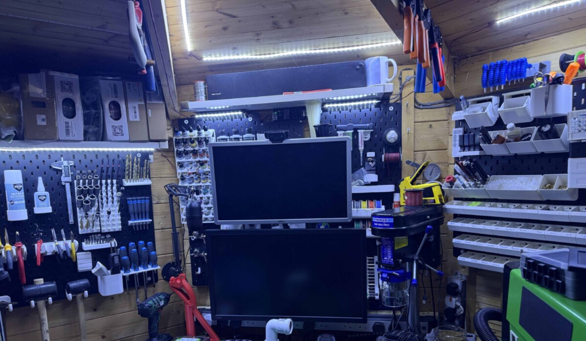
as i have been spending alot of time getting everything printed for the next step i have been customising my octoprint layout and feel. also on christmas crafting for friends and family so yes been a fun week that and i am re jigging the work shop as need to add storage for extra tools as need to make it all work.

High voltage side.

time to look at power supply and lable up wring before i strip it out the box. next up power input and switch. I will be making new wiring for all power elements. First up adding the mains power plug and switch. looks like the are going to need a little help fitting so out with the dremal and they now fit. as it cold have stopped halfway through the job as working how and where to route the wiring and fit the ssr to the psu.

Also, going to wire the printer PSU through a 5v relay so i can turn the printer on and off through the raspberry pi cover this in the Low voltage side of the board but will cover that later.

Low voltatge side.

Now i have the power run across the board I will either add the bucks converter to step the 12v down to 5v to run the raspberry pi or I will use a mains adapter this will allow me to shut down the printer where as the other way would be a total power off. whilst I think I will install the pi and the main control board. am then going to install 2-way relay board so i can switch on/off the machine and lights via the relay.

Time to connect all the power wires and the heater wiring to the board and the SSR.

Now to add all the board inputs and output so end stops motors and sensor

next, it is time to fit the 120mm fan to keep things cool as its a 4 pin I will only use the 12v supply as should work will test this theory later also waiting on t-nuts so I can bolt this to the frame should have them later on today so will finish wiring ready to bolt it all together.

got one more print to go on as adding halo light to the camera so I can film all the loverly creations that I am making with the printer but that will be done once I have installed the rest of the electronics. going to make the camera mount a little more sensible as i feared there’s a little bit of a wobble when running.

testing halo /focus mount is not 100% right but fits and works soldered some longer wiring i will be

As I am waiting on parts as amazon let me down I will be getting the last bits sorted ready to bolt the boxes to the bottom of the printer. ok been a week had a family issue that’s now come to a sad conclusion. so back in London will try wrapping this stage up by Xmas but see what happens.

How my plans have changed

its been 2 weeks of hell over Xmas father in law passed away suddenly so was in wales for a week then came back to london and wife and son both have covid so stuck in london in the house i am negtive and they are both ok.

bad new but good news been working on the project and ironing out my kinks with it so where to start

It dont fit under my printer bed like its ment to due to my custom bed so instead of having a hissy fit throw 70 hrs printing. I am going to let be and will figure it out as i go i have welded the 2 sides together with some high strength glue and exsellitator now bonded together

i then have added some custom stand offs for the fan speed controler and 2 channel relay. i then drilled holes for external raspberry pi power and for fan controler knob. oh and power connector for the halo.

bit of wiring changes to the printer can be powerd off and on by the raspberry pi also using the 12v psu to power the halo light as well also had to change the wiring.

and we are good to go i am waiting on the next mods to show up from the far east got one PCB board still to fit so before i bolt it back together and start testing the new fetures

ready for install just power headers for the pi and add USB PCB when it gets here.

I will leave this here. get ready to part 5 this will be the final part i hope. so whats coming well a UPS 12v board from big tree tech. New fexable bed for the machine and fliminet runout sensor from big tree tech and upgraded linier rail upgrade and thats it.

i think after that i have run out of mods.

see you all in part 5.
CR-10 Upgrades part 3

Well as I await parts I will be working on a few issues and also designing some parts.

What I did not mention in the last part is I managed to drop the control box moving the printer back into the cave as it’s so big and the doorway is so tight. it is back in the cave no so I need to do a strip down and see what’s making my Y-axis go in reverse.

I have a feeling it’s damaged cable or end stop both are on order so should start on this shortly as really thought I had come to the end of the update journey. But no it’s become a paperweight well hopefully not for much longer.

So in part 3 plan is as follow.

  • Fix reversed Y-Axis after drop
  • Time to invstigate whilst i wait for new bracket
  • Fit proper X-axis linear rail bracket.
  • Reinstall hotend with direct drive & Install new hotend part cooler mod
  • Print a camera mount:

Fixing the reversed Y-axis:

this was working right till the control box that was balancing on the bed fell off and dangled. now the printer when homing goes in reverse. very odd I have ordered a new wiring loom and end switch. going to start by swapping the bent up end stop. that main pull was on and replace y loom fingers crossed. The end stop has arrived going to fit it now and see if that fixes the issues. If not back to waiting for the loom.

Looms arrived was the Y-Axis end stop wiring has broken out with the old in with the new.

Installing the updated motor mount and bed upgrade:

After ruling that wouldn’t fit the mods and I didn’t think they would fit.

I changed my mind and thought what’s the worst that could happen? So have fitted both the bed wasn’t too bad once I had lined up the centrical nuts up. I then added the new motor mount this wasn’t as much fun, as mounting it needed some parts that were not included. fist up need M5 T-Nuts luckily I had some, countersunk m5 screws again luckily I had these. right now to reattach the Y-Belt to the motor and the bed. for F#&k sake the belt is 100mm too short. looked through my draw of printer parts and spotted gt2 belts was a loop cut i and then rethreaded the bed. ok no to reattaching the end stop it wouldn’t fit as the holes in the bracket are for the raw small micro switch so have mounted the original end stop back in place if this causes issues can modify the end stop to fit on the brackets with old bent up microswitch scavenged for bits let us see hopefully not but have a backup plan.

all back together and homes ok so now for the next part of the project.

Time to invstigate whilst i wait for new bracket:

Now that I have a working printer going to do some more testing to see why it’s not printing right.

ski jump did hit camera mount im testing for later. bars hav foiled my install idea.

right has put a spirit level and my z was out slightly so have adjusted one of the rods. and the new result is better but still off. Hoping on the bracket to sort this out a bit better.

Just waiting on the arrival of the X-Axis bracket now as I am sure there that that is also compounding this. So as you might have figured I am doing other bits whilst I wait and updating this post as I go. Hoping by the end this will be an awesome printer.

The bracket is in the UK just waiting on delivery so probably in 48hrs time. so time to strip off The offending bracket and strip down the hot end ready for the new bracket to arrive

Fit proper X-axis linear rail bracket.

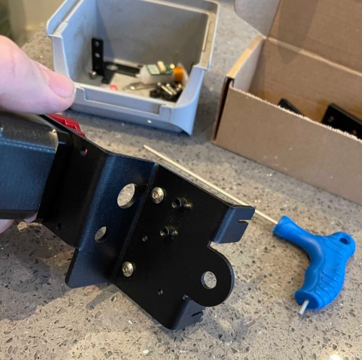
Out with the v2 bracket as there’s a 5mm difference between the centres. as you can see I have removed the modified direct drive hot end as I think this is also the issue with print being fine on one side and in the bed on the other. time to add the bracket and fit the 2 screws. before moving on to the hot end and direct drive. it fits but!! mgn9 rails kit not 12 argh never mind ordered new rail so will sort this out next week.

Reinstall hotend with direct drive & Install new hotend part cooler mod.

I have repopulated the direct-drive motor I have rotated the motor for cleaner wire management. I will now reattach the hot end and fit the modified parts and hot end cooler as it uses existing fans and screws. I had to get my craft knife on it to make it fit but fits fine

I have reattached the BL Touch need to measure the offset form probe to the sensor in the x-axis its -41 and in the y axis, it – 5 so will need to recompile merlin to get it working to make a note of the setting for later. I am already going to need to do this when I add other functions to the board that i will cover in the next post,

Ok next issue

just did a test moving the extruder head to make sure it homes ok and there is a bolt head hitting the z-axis bracket so I have solved this by swapping it for a button head bolt that now makes contact with the end stop so homes fine.

Right, let’s run a bed visualizer scan and see how it is now.

about a mm diffrence across the bed

So out with the solid mounts and I think i will be adding back the springs if i can find them if not will order a set and go back to configuring it manualy.

So back to my box labled printer parts to see what i can find as i have a feeling i saved my springs. YES I did saveI them so will fit them going to to look for some nylock adjustment wheels on thingivers so i can lock them in possition

me being me put the springs back in and spent a hour getting bed as flat as i could before i set saving the mesh and dong the z offset.

Much better

Time to print a camera mount:

I am using a c270 Logitec camera as I do on all my printers as nice and cheap. doh printed the wrong parts need to find another fixing bracket as printed vertical mount instead of horizontal one never mind. Just a few more hours and then will cannibalise a second-hand c270 that I have ordered so inserted about £24 on amazon and got it for £13.

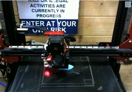
I have used this one before and it worked well so I pre-printed this design that can be found here. All you will need is some m4 nuts bolts and 4 t-nuts is fixed to the framework like so.

ok, it’s probably going to vibrate like a bitch but I’m game for a laugh lol.

view from the camera lol

Right now up to date with all mods, there are more to come but going to make sure I have a functioning printer before I go splash out on any more parts.

Calibrate and do some calibration prints without issue,

Now that all is working let’s start to play with calibrating the machine and getting it all working right. so first up is a bed levelling program not sure if I need to run this at the start of the print each time. can make it fewer touchpoints and then to calibrate z offset height.

Still needs a bit of a tweak I think will do a few more adjustments to the springs to get it just a slight bit more level as seems beds off a slight bit. I now remember the pain of manual bed levelling but hope it will be worth it.

made some firmware tweaks let see if this fixes the machine. getting there nearly dialled in just got to drop the head a few 0.01s and we should be good for a benchy test.

All sliced up ready to print think that will be tomorrow

Success i have a printed bentchy will be looking at it properly when i get home later.

so got home had had 1 layer shift so have tightened up the belt and run the print again. now yay had a filament jam and a tangle that made the print fail halfway through so I have decided to 1 make a better spool holder for the printer and 2 go back to sold standoffs or silicon ones so some play but can be locked in a level position.

so whilst I wait for parts again printing spool holder.

Now to glue and fix it to the wall.

It all looks like a good time to print something bigger before I try doing 1 day 12hr prints on it.

eureka is all working well now to do some calibration prints to make sure all is well in 3d printing land.

so after 5 calibration cubes and a benchy or 2 or 3, I think I am nearly bang on as level as I will get it with a bl touch across the bed.

Conclusion to part 3

Now that I have a working machine I am going to turn it into a pro by losing the control box.

don’t worry this will be part 4 as having a working printer that’s improved the prints and has improved the quite ness of the machine, not the control box but that will be part 4.

but back to the big print

well, about 2 hrs in and it’s printed 2 layers a little bit of stringing but let’s see going to risk leaving it alone for 2 hr or more. ok came back 6hrs later and yes it’s still working I am amazed my self oh well 1 day 3 hrs left on the print.

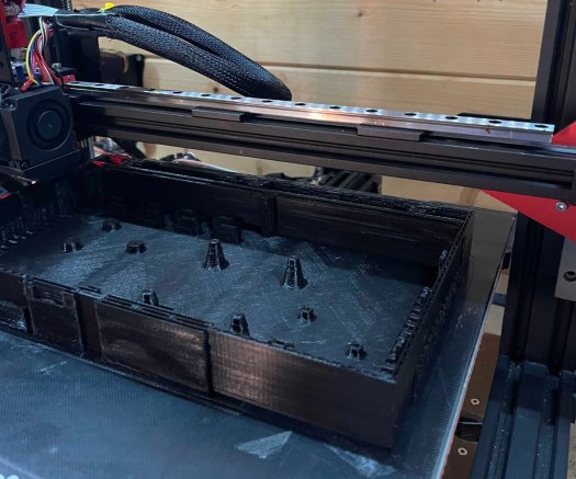
Morning all well been printing for 23 hrs now and still going a strong slight bit of warping not bad and won’t affect the massive print this is side 1 of 2. Apparently, 23 hrs to go but it’s 61% complete so I think it will be less.

Happy the machine is working right so will show the finished side a put a pin in part 3 get ready for part 4 more modifications coming up going to order Y linear rail upgrade so we can start speed testing.

35hrs 10 mins and she is done this is pcb side low voltage.

right, this is the end of part 3 as 35 hr print is complete and looks great. did thteh enw feet over night and now doing the rigth hand side so another 35hr print.

then wehen i get back from wales i will print the lids, and start adding the electronics.

but thats going to be part 4 over all its working well so let see how we go now 1% in to next large print.

Part 4 will be all the 3d printed parts and part 5 is going to be the linear rail conversion on the y-axis.

next post in the next week or so.