you will need a licence for fusion 360 I have a free hobby licence that is limited but till i get time to learn the cam side of the program it’s free to me unless Autodesk feels kind and wants to give me a licence. not that they will read this anyhow.
open up fusion 360
the file I am going to remix is this spray can holder.
Now to remix it or in this case, I am going to create 2 bars for aligning it on the wall by using its original parts as a template. over to fusion
then go to insert drop-down insert mesh
you then can position it how you want i this case will keep it as it is so select ok,
now press s on your keyboard then type mesh you will select convert mesh.
Now select the stl
then hit ok on defaults as all other options only in paid verison.
sketch will now look like this
at this point you can simplify the sketch and make it fewer polygons by selecting segments and removing them hitting delete as shown below
selected poligondeleated smooths up shapepartly cleaned
So why do this well on flat surfaces makes it easier to select planes.
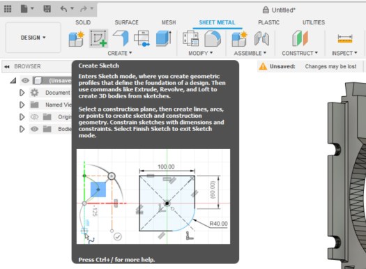
go to the sheet metal tab select Create Sketch, you are now going to select face to edit.
select highlighted plane and click you will now see it like below.
I am going to start off making a bar so i am going to hit L on the keyboard and will give me a line command.
as I am using snap to have determined the endpoint where I want to start the line click mouse to start the line
I next go to the bottom right corner of where I want the box i am making to be this will give me a guideline.
like below can now draw the 2 lines needed
close the shape
Now hit enter.
so that is literally the only bit i need for my idea but actually going to 2 as I want the top and bottom lugs to make int to alignment bars. so going to repeat this process and then we will continue.
I am now going to remove the original part from the system as i have the 2 elements i require for the alignment bars as will be easier than removing all the material I don’t need.
then hit del and sketch will remain
now to extrude it on both parts 100mm as think it’s a good size so hit E on the keyboard when selected object
hit enter and repeat on the bottom section of the file now change view please not i have moved them together for illistations.
Now to make the parts you now want to go to utilities tab select make
select the parts and in chose options as 2 body will need to do this twice.
this next part is as I have set my Prusa slicer to open when I make them so at this point you could save them as stl
now the part is in my slicer i am going to set it up for print by changing position before i save it out as an stl.
first to make it flat to the bed i will use the place on face tool F for a quick keyboard cheat
will select the bottom face
part ready to print in this case going to save it as a stl.
click the part then right-click and select Export as STL
save and parts done. then added them to one file ready to print will show more detailed remixes soon
then its over to the printer via octoprint in my case and away it goes as i have doubled up the parts as to racks going on the wall will take 2hrs to print.
parts all done ready for a test fit.
perfect fit love now to glue them all in place.
can find my files here do love a quick 1 day project parts are in to finish off the cr-10 so that should be up soon.
When you know how to make 3d models and prototypes 3d printer is one of your biggest assets in the small workshop. this whole project took 4hrs 30mins to complete from idea to finished working design and 4hrs of this was the print time.
Back story
As I am currently waiting for virgin media to fix an issue with my router before I can make the new website live as need to port forward from the VR machine. So to make sure i can just start to work on projects I am re-laying out the workshop. I have had tools sticking out of dump bins as I didn’t have a space to place them it’s got a little out of control. so back to the problem at hand and the point of this post.
The issue
Bocsh Wireless glue gun never found a handy spot for it. so last night after pulling out my callipers for some ruff measurements. I decided to make a handy wall mount.
The MountDesign
So fired up fusion made a 40mm circle and extruded it to 55mm then added a new sketch and made a new circle 35mm at on end of the cylinder I then cut into the cylinder 30mm I then added a 5mm hole through the middle and then using a bevel tool made a cone to exit.
I then flipped the design on its side and made a 55mm x 30mm rectangle I then moved it from the central axis to the outer edge of the design and extruded it by 5mm I then added 2 countersunk holes. by using a circle tool and the bevel tool. Now to export it to print.
Now to drag it into Prusa slicer and slice away made this design so won’t require any supports of rafts to print. printed with 25% infill. gcode ready for upload to octoprint. Away we go overnight parts was a 4hr print left it going as having rigged up relays for the lights and power of my printers so once completed it will shut off.
The next morning– The result
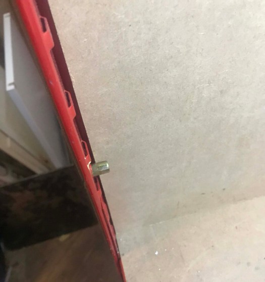
As you can see worked flawlessly apart from me being overzealous with my talk driver screwing it to the wall. but it’s perfect for my requirement.
My next job is to add a keyboard draw to my workbench using the track system but need to go grab some bolts and 50mm x 50mm wood from the local hardware shop.
Started stripping out the old hardware going to use a perspex window mounded to the unit with some flat head threaded rivets. Screw knobs 6 on the big window. then going to buy a A3 sheet if perspex and drill the 2 corners and cut a window out of the tool end with the same side panel but hinged on the top end. with to thumb knobs.
going to find some brackets to print to make the enclosure more scure.
will make sense when you see it.
Still not sure if i need a better dust collector going to get a mask as mdf is nasty stuff.
Going to re-run line vacuum line as it pulling the board also going to look at 65 mm dust shoe. to print.
But will work on that going to mount a camera on the outside of the enclosure looking in as the go pro went flat on me last night. then should be able to get good footage.
will start the documenting of it all tomorrow.
Starting to look at doing some fun stuff think i will get some hard woods to play with.
started looking at some dust shoes last night found one i realy liked the look of but its missing the brush part of the shoe. lots of people asking designer for it. no responce unlike most people who would just find another one. i desided to remix it with the brush attachment.
So pulled stl in to fusion 360 i then used it to reffrence shape and made the rest as i whent looks nice now to test it so first job of the day when i get to the man cave is to load the printer with some Petg and print this out.
the part i designed is in grey on the image below.
bit in gray is what i designed as was missin from downloaddivits are for 6 x 2 magnets
I also made a inlay for brush strip to be inserted.
now to print it all
Just waiting on the wife to wake up from her sat morning lie in and will put some petg on the printer and start the print looks nice and compact so hoping will be more effective than the last shoe. as was a little bulky also means i can leave brush off and show you the cutting in action. as just held on with magnets. more later.
first part done now to test fit before i go any further.
First part printed will test fit it in a short while need to still dial in the other printer would be doing this with both running.
fits like a glove will now print the cavity part back in 4 hrs if i am still up and then will do the final part the bit i made and hopefully it all fits together. by tommorow will have a working dust shoe so far its nice and compact need to find some brush for it as mine is too big.
after diner will mark drill and make large observation window and make a mock-up for tool change window. then going to fire up my birthday present from wife a mini router and cut the window out that will probably be tomorrow if time allows. will then order some 4 mm A3 perspex and do i attempt to print my own hinges, hmm maybe i will to save some money.
also going to look for a enclosure camera mount or something that will suite my application.
So a bit of graft with some research more later
Ok! I sat down mistake I know just printing tonight will get this one off the bed then i will get the next one printing so by morning i should have a working prototype now to look for brush for the shoe.
second part done
Right 10 min cool down and will go remove it from the bed and start on the last part hopefully will all fit together.
away we go night all back tomorrow for more fun.
from design to production in less than a day do love 3d printing.
Morning all well afternoon had a lie in this morning was a late one. but parts are finished off. Will go down and see it fits before i apply the magnets as i have limited supply.
Just need to do a test fit. and find some brush. in fact that what i am going to do now.
It fits like a glove going to make a custom brush for it shortly might cut a broom down and hot glue gun the bristles in place.
Perfect fit now to add metal and magnets
underside
will post remix shortly on Thingiverse and make public will post more images shortly once done hoping to do more on the enclosure later.
to make the above you will the following parts off Thingiverse.
Right Fitted the hardware and magnets have fitted it to spindle works well and is nice and compact has great suction too. just need to make the brush up next. not sure the best way to do this might buy a roll of PVC door blind material 2mm. and cut it down then make slits all around for brush part. limits are spot on got to love fusion 360 love my hobby licences free to makers and such a powerful tool i still need to do a course on it and learn its full potential.
Hardware and magnets inserted no need for glue limits spot on.fits like a glovezoomed out shot will do test tomorrow
Have started to drill holes for rivets i will then drill 2 fixing holes and mount perspex on to thumbscrews will drill these holes slightly bigger as gives me movement after i have drilled it then will drill a further 4 holes to racking so six screws in total. Drill batteries went flat waiting for a charge. before i mark and drill other holes.
2 holes drilled 4 to go then rivet time.
Think i will then move the suction hole to the top of enclosure might cut vacuum hose using 40 mm pipework to run a cleaner line to vacuum. going to do a test cut and see how it performs now with the different shoe.
Going to do that tomorrow as getting late again. will take a couple more shots later when i go take the battery off charge.
2 rivets in the hole just need to squish them need to change the head from 3 mm to 6 mm might actually do all the 3 mm holes first so i can then just concentrate on the 6 mm.
time to sleep back tommoorow.
Right been working on a day job in the man cave but have had time to drill and rivet all the side access holes.
I am going to get some cheap opaque 4 mm perspex from the local DIY store. and some insulation foam tape to stop dust coming out.
But that will be tomorrow as will be going out to the office. so will stop on my way back.
found a sacrificial broom to cut the bristles out of and glue into the shoe well that’s if i can get it to fit. The plan is to cut each bristle in 2 and put masking tape around the middle to holder them together till glued.
Will post images later. Going to run test cut tonight need to do some side projects for a friends gift but won’t cover that just in case he sees it.
Test run worked well wow the cave heats up and the vacuum is very noisy might have to see how to get a quieter vaccum.
Away way we go going with less dept and and more speed.
It turned out well going to need to do some minor sanding then to paint it.
all v bit cuts done just end mill pass to run
Just need to run the cut out pass but will that tomorrow happy with my progress going to get some different woods to play and some aluminum.
New 4 axis mpg.
Managed to install new MPG had some issue installing as it was not quite registering as in showed up on the PC but wouldn’t move. was about to send a shitty email to the ebay seller but. held off i consolted google and came up a blank i then remember last one dident like usb 3.0 plugs so I tried that. it then worked i will now to set up the macros as then can press button to do actions.
Did find a video on adding custom macros as want as the system uses it uses its own z prob script. the video showed how to get the mpg to work with 3rd party macros. to add z probe function and a few others. so i will start making a list of macros to add to the mpg. that might be a job of the day as the weather is not on my side today.
Will be going to the local hardware store later for some perspex and wood later. i managed to mark out the base board for its window cut out if the rain lets up later will cut it out when my son has is nap. as then can start putting things together. ready for perspex sheeting later.
little hard to see pencil marks but theirs a window there this is for quick access for changing tools.
right i will update more later if i can get it cut out today. the sun came out and the son finally slept window is now cut now to wake the boy.
Tool change window. now to seal it all up and make it dust proof it.
Tonight will screw it all together and make it as dust proof as possible. more later on this.
back from DIY store, i couldn’t get any perspex so got a sheet of 6 mm MDF will make it out of that for time being COVID-19 limited supply’s.
have marked it up ready to cut sheet down and add holes and rivets then will use foam backed tape to act as a gasket, will then use 3 x M6 screw knobs to hold sheet in place.
Cut the sheet down using my bosh multi tool cut though the MDF like butter. The MDF is temporary till i can get perspex. The joys of covid-19. i then drilled the fixing holes for the panel i then held up the MDF in position. I marked thorough the drill hole on the mdf. i then drilled the marked hole. I then fitted first flat rivet in the hole and fixed it in place with the rivet gun. then placed the MDF back ant attached it using the plastic M6 knob. I then marked up the renaming 2 holes. I then drilled them both and applied rivets to both holes.
New tool door quick access.
I then attached 6 mm insulation tape all around the window to stop dust escaping
lots of foam tape to help dust escaping.
I have also attached cabinet edge blocks through the enclosure to seal it up. need to get some more duct tape to seal to the racking.
its nice and snug
will take some pictures shortly but happy with it so far just need to play some more the system i think I might get a 1m hover extension pipe so it can be plugged in and out.
will measure that tomorrow and have a look at options.
have reprogrammed the mpg script so my z zeroing prob will now work on the mpg just need to figure out what custom macros i am going to install to it.
and it works liking this.
with to door off it gives great access to the front with 3 turn screws about 3 turns to release front and six to do the sides.
door open
I have a few bits to add to this project but they can be done as when i will update and post.
Finally after 4 weeks of waiting my upgrade is here..
So whats in the box?
So after an hour of taking your old machine a part you will get to section 15. So all i need all the stepper motors 2 pulleys the led screen cables and cover if your sticking with the colours and that it. Everything else is new. Oh, and threaded rod lifters missed that.
Next up the printing now if i did not have PETG in my collection I would be doing a 36hr print using the 2 rolls of pet supplied with the update kit. But as i have been prepared for a while i did this in Ultraviolet PETG and Black PETG. parts already printed.
Now to let the fun begin. armed with my own Allan keys and magnetic dish and the free Haribo Goldenbears. That will keep me going time to build my self an Mk3s. this will be over several nights as like taking my time it can be done Quicker but I am no pro.
Y-axis and frame are done
so is x managed to crack a part so going to reprint idler side of the X-axis whilst i have put violate back in my Prusa Mk3s .
I saw when building Y-axis that Prusa has updated belt tensioner. so that’s going to be done overnight as well.
10% in then i can get x finished.
also couldn’t go any further i missed 2 bits off the list of parts and thankfully there in storage so i will need to swing by and grab them tomorrow after stock check at office and meeting new tenants.
so will resume tomorrow loving the colour.
been a stop start as over night parts fitted but then noticed motor end was cracked so reprinted it. 4 hours.
I then realised updated parts need different motor mount as they won’t fit if not. so back to old-style as could not bare another 4hrs print. and wanted to get it built. added the missing trapezoid nuts that i retrieved from the storage unit.
so finally fitted Z motors and rods added X axis to Z axis. and screwed it all done.
Went to start the extruder and soon realised the link i had been given was mk3 not a mk3s so i am now printing over night the upgraded bits.
So that as far as i can go today.
back on the shelf till tomorrow.
parts off the printer and off we exstruder motor monunt fitted hotend installed and magnets for filament sensor all installed. righ now to install the x carrage. oh its diffrent looks like another 4hr print. missing 2 bits as the x carage has 2 parts hoping this i my last delay in the build.
all done hoping last delay
think i might run thought the rest of the instructions and make sure they haven’t updated anything else. pretty sure it was just the extruder they did upgrades on but going to have a quick look.
exstruder all done. time to fit to the frame.
Was a late one last night managed to build and install the extruder fit the PSU and LCD oh and heatbed.
Now on the home straight wire management and controller board and we are done on the build hoping to do that at boys nap time then just pre flight checks and we are good to calibrate.
Wiring and cable management time..
all wired preflight checks done time to calibrate my machint.
All done and z height calibrated now to home ultraviolet the cave make sure webcam is in the right location and we are good to go. the mark not the screen is as its off old machines managed to damage a while ago but works fine so not going to change it.
Z cablibrated moved in to its home
needs some web camera adjustments do them later.
will do some calibration testing later now to print the spooler in orange and new control knob for neon orange. will update more later. give my summery of the upgrade kit and build.
Ok sorry for delays been a labour of love as have had issues the setup and getting wiring working right. but here we go. for time being i am going to simplify this post as serial links don’t seem to be working right will have a revisit to see what’s going on. might rework the wiring loom i made to see if that solves the issue. so running on USB
and even then last night had issues with that was trapped wiring, in the end, i have also ordered a 90degree USB cable to give some wire relief.
New USB cable seems to have fixed all issues with the printer sending kill cmd.
After having issues with my 3.5 TFT screen I now think this might be down to OctoPI-TFT not being a fully working build as i have rebuilt on my 3.5″ screen and 7″ to limited success. so i have decided that i have a 7″ touch screen and enclosure kicking around the man cave so i am going to install TouchUI on another pi yes got a few of kicking around will be directly linking via USB as serial links playing up. will also be installing power management with the plugin to turn my Original Prusa i3 Mk3s on and off independently to screen. also will be adding a led lighting ring around my web camera. this will be controlled by my octopi server using GPIO pins.
So what are you going to need to attempt this
7″ touch screen and enclosure.Raspberry PI 3
1 x Raspberry pi 3
1 x Micro SD card 64gb overkill but smallest SD cardi have bar one in current set up.
1 x Offical Raspberry Pi 7″ touch screen and enclosure.
5v Arduino compatible relays. in my case 2 channel relay.
some duplex sockets and pins numbers to be confirmed.
crimping tool.
wire strippers.
wire, in this case, using a 6 core cable and a few single wires for lighting and any other additions as i build this project.
Let’s get started First of all head over to Octoprints web site https://octoprint.org/ and download the 600+meg image start off by downloading the latest image.
you will need to unzip the image an image writer to burn it. I use etcher as it’s free and quick, select your image then select sd card as the target then hit start. a window pops up say yes to off it goes. will take around 15 mins to write and verify the sd card.
Select image from where you unzipped it.Press start to write to the sd card say yes to the windows scurity alert.off it goes time its verified will be 10 to 15 mins.
Now install the memory card into the pi and insert into the enclosure.
Then the power unit will reboot 2 times whilst it configures bits will be left with a screen showing the system ip and telling you to set up pi via the web browser.
Now time to install some bits in the background so we can tun this into touch screen printer controller.
You are now going to have to get an ssh client. i use Bitvise SSH Client as again freeware and very useful tool. so in my case i login to 192.168.0.50
you will then be asked for the default password of the pi which is raspberry. first things i tend to do is rename the host and change the default password. one to secure the pi and 2 to make it identifiable on the network.
type the following sudo raspi-config hit return this will then bring up the config menu. will get some legal bits about privacy and then be asked for the password again raspberry.
option 1 to change password for rootenter new password 2 times
You will then be greeted with the following screen
password changed you’re now secure.select option 2 the option N1 Hostname then enter to rename.then hit ok
Now go to finish you will be asked to reboot say yes. the system will reboot and you will need to open a new terminal window.
Bitwise will let you know when its back lives in my case can see it across the room. you will be asked for the new password when logged in click the new terminal window button will show your new hostname.
Now time to configure OctoPI with Touch UI Plug-in.
go to localhost.octopi or IP address that is displayed on your screen on boot up
First, of time, you go to the octopi web interface will be greeted with a wizard screen.
Start Screen
Access control you will need to make up a username and password. then scroll down to enable login.
Online Connectivity Check I enable this
Plugin Blacklist I enable this.
CuraEngine (<= 15.04. I skip this as all my files are pre-sliced.
Default Printer Profile. Name your printer and profile also set up bed sizes in the tabs in the case of the Prusa mk3s it 250 x 210 x 210.
Now to do a quick plugin test run with my Prusa machine.
insert the basic screen.
Right now we have proof of concept. time to get on with making some connectors up and wiring to link to my Prusa using Rambo serial port. So as my other posts have found out the Prusa serial port does not have the amount of power to power a pi3 without the system having external power.
have clipped the red and black wire off as not using power from Prusa printer. going to make a 2×2 pin duplex female connector with blue and white wire and one with yellow and green. these will insert on to the following GPIO pins. 08 = white 10 = blue 15= green 16 = yellow this will give serial connection via Rambo board.
have included this GPIO pinout guide off element14.com website to aid with mods.
time to test again to make sure all connect correctly. success at last!!
Now to add power management and lights for the camera.
Now there are lots of ways this can be done using wifi plugs or relays in our case as want to make this a fun project going to use some 5v relays i was going to use some individual relays to make this project work but i have decided that i will use a 2 channel relay PCB that i will house in a housing as don’t want any wires sticking out.
Let’s make a start.
Taking note of the GPIO pins your going to use with this project in our case we will be using 2 x 5v relays so will use GPIO pins 04 for 5v+and 06 for ground.
IN pins will be any GPIO pins free so in this case, going to use pin 38 and 40 so GPIO20,21 as the triggers. for each relay, as will only use 2 to start might downgrade the relay at a later date.
Found this predesigned solution for 2 relays so will give it a go on Thingiverse
i then jumped on PrusaSlicer and added the stl files. sliced them ready for printing.
not quite a perfect print but will do for the relay box.
Now have printed the relay holders will start on wiring side first one will be using 12vdc for light ring low voltage the other relay will be running mains voltage so do not attempt his if you are not comfortable with mains voltage. this is for UK spec wiring colour codes will change and if you’re in the states will not have an earth wire.
Let’s start with the dangerous element well not really that dangerous just be careful when messing with mains cables.
I tested it on my 4 channel relay to test the theory with GPIO pins switching without any power circuits connected to make sure it all works before adding mains voltage. my 2-way dual relay should be with me tomorrow. should take out shares in amazon as my prime account is much used.
!!!DO NOT HAVE LIVE WIRES EXPOSED WHEN PLUGGING INTO THE MAINS!!! makes sure all wiring is not exposed for anyone to touch i my set up i have mounted housing to back wall of the man cave keeps everything out general reach I also used terminated connectors with plastic sheathing to keep everything safe as a mains voltage shock is not fun. I have worked with high voltage for a few years and have been shocked several times the joys of playing with arcade machines and other industrial equipment. this is a disclaimer only attempt this if you feel confident with 240v wiring.
Relay 1
As i have a million and one kettle leads kicking around take a spare one and strip the outer sheath from it without cutting inner cores. i have a special wire cutter to do this and some wire cutters.
outer insulation stripped off i used coaxial cutterwires cut then stripped .added crimp pins i am redoing these in smaller pin size. as the yellows are too big squished them as a quick fix as testing.240v end wired and strapped down.
You will be left with the 3 inner cores. cut the brown wire and strip around 5mm off each end. these wires i use pin crimpers as seals wire and makes it neat. the two wires will go into the high-end voltage of the relay so one will be on com or common pin and the other one will be put in normally closed or NC pin.
Relay 2
This will go via a mains powered 12v PSU i have wired this into the mains and taken some red and black-led wiring cable i have cut the red live wire and stripped 5mm each side and placed pin connectors on each end. placed into Com and NC connection terminals the same as above.
Low Voltage side of the relay to Raspberry Pi 3
on the other end of the relay, on the low voltage end, you have 3 pins IN, GND and VCC IN= GPIO pin GND = Ground and VCC= voltage input. GND and VCC will share voltage for the 4 relays. so will wire IN1 as the mains power switch and IN2 will control 12v lighting ring. leaving IN3,4 free for additional bits for the enclosure. so will make up 2 female pin duplex connectors one with 5v and ground. and the other 2 pin connectors will control lighting and power relay inputs.
low voltage wire will change with 4 pins instead of the current 6 pin
now the wiring is complete time to install some plugins.
ready for 12v PSU and mains voltage just going to test relays before install 2 relay PCB
all boxed up new 2 channel 5v relay ready to wall mount just going to make appropriate length cables.
tonight’s effort as most don’t realise this stuff takes time and has taken me a week to get all the bits together. tonight rewire operational and case installation. also testing plugins and doing an 8hr print. wish me luck.
Wiring swapped over to 2 channel relay and installed in housing.all wired up ready fir 7hr test.
then armed with a hot glue gun i have glued my led ring to my cheap C922 Logitech webcam. some crimps and cable ties all attached i found an old hard drive power supply 12v that has 5×5 2.1mm power plug. to the parts to grab a female of the plug that i have so i can unplug it easily. The light is on now to install some plugins to control it.
Right ready to test just testing light as till i have a case for the relay i don’t want to risk mains voltage
i am currently testing out different plugins but work well.
Lights off
Lights switched off in my dark cave.
Light on all controlled by a plugin.
print for enclosure is done just need to pull it off the bed and fit the 2 channel relay to the box.
Ocoto-piPlug-ins
going to run this through the enclosure plug-in so i will be able to power on and off the printer and USB camera light.
let’s get started
Touch UI plugin.
Go to the plugin management scroll down to get more and then search for touch UI after it’s installed you will be greeted with a request to reboot. do so
This screen will appear after reboot
when the server reboots you will be greeted with the new interface on the web log in don’t panic can switch this off look for the 3 bars on top of each other to the right of the screen. Click on it and sub-menu will be displayed click on TouchUI settings
click TouchUI Settings.Click Toggle TouchUI to disable it on the web page.
The screen should go back to normal now.
Next step is done via remote terminal screen to install the front end for the 7″ screen.
Login to pi via ssh and do the following. Type the following to get the installer script.
TouchUI should now display on your small screen were as a web login will be the same. you can customise it via the plugin under the web interface i made mine orange with black background.
Now to add functional add-ons to the system. will be installing a posting my findings in another post as this has been a week of tinkering but now happy with the output.
around 4 hrs till this finishes then will be adding add-ons.
nearly 4 hrs into wall mount spool holder. looks great.
Will be adding the following over the next few days and hard wiring the build.
Simple Emergency Stop
just what is says it i adds a E-stop to your menu bar as things do go wrong i usually sit watching the first layer or two print before going about my day and check in every so often.
Heater Timeout
this plugin saves your ass if you have forgotten to turn off printer hotend will allow# you to add a time out on hot end being idle.
OctoLapse
The daddy of time lapse captures with this powerfull plugin can make prints appear from nowhere. took a bit of reading to get this working right but worth the hard graft to get it working. mind you there is a pre-compiled version for the mk3 so might just try that.
Themeify
This is great custom themes discord being my favourite as i do not like white backgrounds.
PSU Control
this nifty little plugin will allow automatically shutdown of the printer after the print has finished also allows you to remotely turn on and off the printer.
OctoPrint-Enclosure
this will allow for all sorts of inputs and outputs i will be using it to switch on and off camera LEDs and maybe more in the future as might add temperature sensors in the future.
OctoPrint-PrinterAlerts
this plugin pauses the print if there any errors from Prusa printer sensors a must for a Prusa user.
FilamentManager
Filament Manager for OctoPrint yet to try this but seams promising for knowing how much is left on a spool will document this as i install. it.
This OctoPrint plugin helps to manage your filament spools.
Replacing filament volume with weight in sidebar
Software odometer to measure used filament
Warn if print exceeds remaining filament on spool
Assign temperature offset to spools
Automatically pause print if filament runs out
Import & export of spool inventory
CostEstimation
this allows me to price up my prints even if they are for my us as good to see how much i am spending.
OctoPrint-Complicated
As the wife has brought me a new iwatch for birthday i will be using this addon to see how my prints are doing via the iwatch.
OctoPrint-Dropbox-Timelapse
allows all captured time-lapse videos to be uploaded to my dropbox to stop any issues with my sd card filling up.
As i will be adding a Pi3 and octopi to manage and control my machine i was trawling through Thingiverse i spotted this little beauty. Thought would save me space and can integrate with the Prusa machine i also have 3.5 TFT adafuit display kicking around my bedroom.
Got this remixed design from FlyByTom this version V7 with no end cap. i went with this design will completely integrate into the panel this will mean can plug into the pi3 for USB and network connections when. I will be using the jumper pins from the back of the TFT screen to the Rambo board this will power the pi and integrate it into the printer. The link for the design can be found here
Downloaded and jumped into Prusa Slicer followed the instructions and put it on the plate at an angle so it will fit.
ready to print.
i am going to print in PETG when i do the final print but for a test print i have some black PLA kicking around the cave so will do a test run. Then print in petg later as I have 3 rolls kicking around that i have been meaning to print with but that will be a final print later.
The test Print and fit:
6hrs it printed in came out not half bad there was tiny amount of lifting in one corner
The wiring of the PI3 into the Prusa Rambo board. This is going to be slightly different from the guide on Prusa’s web site as will be wiring from the front of the PCB. found someone who makes cables but unfortunately, they don’t ship to the UK so going to have to make one my self.
There are six wires need to link the machine to the pi bank of 4 and 2 are used. so from the Rambo PCB, you will use the following
Pins used on the Rambo board.Connections like so from the Rambo PCB
so to make this as i had no 7 pin connecors i glued a 6 x2 connector and a 2 pin connector together to make it a 7 pin connector. used some breadboard to hold it all together whilst the super glue set.
nicely glued up. ready to solder the other end.Rambo connector cable i made for linking to the pi3 plugin and play.
Now a direct link would be too easy as the TFT screen uses all 40 pins in connection there is a break out header shown in PCB diagram below but too tight to attach connector did try.
failed attempt as heads too long.JP1 is the brake out connector. only interested in the first 16 pins.pins used in the PCB pinout diagram.
as the pin headers are too big so going to have to solder to the pi 3 directly so ignore above brake out wiring will be same pin numbers on the back of the PCB board going to flux and add solder to the 6 pads on pins 4,6,8 and pins 15, 16. I ran out of time to tin wiring and solder and test on Tuesday.
What it looks like wired up.
building the system:
This was partly straight forward partly frustrating as not all guide work. heres here’s my simple version of the guide this guide is if you are Using Adafruit 3.5 TFT display
you will then need a program to burn it to your sd card i use etcher select image select sd card and write 20 mins later will have a working image
Put install screen to the raspberry pi add the SD card and network cable then power the pi will take a few mins to power up the screen will show just as white don’t panic.
scan local ip network for pi in my case showing on my network as 192.168.0.1 using a ssh client login to the system using user name pi and raspberry as password.
Time to install TFT screen drivers this will get the screen displaying correctly. in the ssh, terminal screen type the following.
when installing the script you will get asked the following. what screen it is in my case option 4 3.5″ 480×320. you will also get asked if you want the screen to display consol. i said no and yes to HDMI port mirroring just in case i decide to use the HDMI port. You will then be prompted to reboot the machine say yes.
you will then need to relogin to the pi.
As octoprint image does not have graphical front end is web-based. We are going to first have to install the X desktop environment, then Touch-TFT and its requirements
Now on reboot OctoPrint-TFT should load and start attempting to connect
this was in the hose so no printer connected.
On reboot, you will see this screen until you plug it into the printer. you will then control screen as shown below. as i haven’t installed my link plug into the Rambo yet this was just to do a test to make sure all was working.
testing the server works. need to mess with the style sheets
now to configure the web interface of octopi.
Open web browser goto IP address or octop.local you will be greeted with a wizard so set user name and password and enable security. name profile of printer and set bed sizes in my case 250mm x 210mm x 210mm i also adjusted temperatures to match my Prusa printer in the configurations folder.
i will be adding plugins but will cover that in another post.
i will finish off this project on my return to London as got a 208-mile drive down to Wales for a weekend of getting holiday rental ready for first guests.
As it was Sunday night and wet i thought i would bring the Prusa in for its upgrade as its time i fixed it once and for all.
One of the perks of being a Prusa owner is when new tech is produced they release an upgrade kit. So armed with a Pepsi Max cherry my electric micro screwdriver a pair of pliers and a screwdriver i set to work.
sunday night fun ready to start the upgrade
got the footstool and a box and made a little workshop in the living room as my little one was in bed.
All stripped down box of bolts removed time to upgrade
so after 30 or minutes or so i had taken apart the old extruder and was left with bare z-axis ready for its new extruder to be installed. now to install the new extruder.
Do love the online manuals nothing missed. what you see on the screen is what you need to do.
about an hour and 30 mins into the build and starting to button up the extruder getting ready. for electronics. section of the upgrade
All done 2 hrs later yes i missed some square nuts and had to rebuild x backplate again doh missed that section of the manual it’s fine as was easy enough to do. right all built.
Downloaded latest software and firmware of the Prusa site ready to flash it. all done flash successfully. Time to calibrate my machine and hope the upgrade has fixed it. here goes nothing. ok seft test passed auto home passed XYZ calibration failed arg going to call it a night as 1 am in the morning on a work night.
Monday evening feeling bit on the tired side. I have managed to speak with tech support online chat and was asked to check the P.I.N.D.A probe yes think i must have been tired as had not plugged it in last night doh. Ok, let’s get back on to the calibration one last check of the P.I.N.D.A probe hight and found it needed some minor adjustments. time to calibrate
4 point calibration to start off with fingers crossed.
Yay, its passed all calibrations and have dialled in the first layer hight. done a simple test print all working. time to move it back to the cave. time to test it’s all working. first long print. 12:30 am fist layer looks perfect time to sleep.
have checked on it this morning and its still printing. So i think i have solved issues with my mk3 will post an image of first printed half of the spool holder later on my return home.
Will put an image of the first half printed later here
That one working Prusa Printer now to fix the Mk2s MMU as then can print multi-coloured prints. without the expense of pallet 2 +. Fingers crossed on that one as then will have a full set of working printers at home. That will probably be on my return from Walse as got a house to get ready for our first renters so a busy week/week end.
Will be printing 5 spool holders so i can have a full set of multi-material printing and the mk3 at the same time.
Have in a three-meter Octagon is not the easiest of places to house as much equipment as i have. also as it has windows on 4 sides. So as i have Wednesday off with my son i had been into the local DIY store to grab some screws bits for another project i have been doing. This was a few weeks ago.
I picked up some 10 cm x 5 cm timber and sheet of plyboard to make a cover that went over the winds so i could mount my parts boxes. i had managed to hand saw down the sheet of ply and mounted over the window.
i then added screwed new parts draw i had picked up in the Aldi for £8.99 and my Budweiser sign. looked ok but was just a place to put parts.
Window cover board that i put to give me more storage space.
It worked well but was not quite what i wanted. I had just designed a template for holding Placemat and Coaster.
New jig for holding wooden placemats as have a dinner set to do for our house.
I then started to run a batch of placemats and coasters for our holiday rental property.
Engraved in Wooden placemat The Hollies Logo our rental property in wales.
As this was running I thought i would make a start reorganising things. so the Budweiser sign has been relegated to the attic. i move 2 of my other parts boxes around and dump bins allowing for a new shelf.
makes more sense having all my nuts and bolts fuses crimps and components in one place.
I then moved the dump bins racking so they were next to each other. I had an IKEA shelf we were going to use in the house. that i have installed for the moment above the racking.
Just got to sort through all dump bins and add to other storage.
i have started to print brackets for filament storage from the 3D printing nerds channel. So i will have shelving for the 2 boxes of filament i have freeing up more space hopefully. However, my Prusa decided to jam yesterday so will have to wait till come back from wales next week to fix.
Just before we it decided to jam up.
As i am working on the map and paid jobs i thought i would get everything up and running and remove bits i don’t need down to wales.
As then can do stuff when i am not in London so my K40 is going to be shipped off to wales along with the Prusa MK2s MMU and clear some space up for stock and parts.
this will be happening next month as will use a man and a van to transport bed and other bits as holiday rental property we have been developing is finally coming online should be available to rent in the next few months.
Next racking unit to sort is the CNC and vinyl cutter as its become a dumping ground and remove redundant bits ie water buckets for cooling as changed for a smaller type.
will be nice to actually get in the cave and be able just to work. Will be adding a download section to the web site so all my projects can be downloaded for free. maybe a project section to get some feedback and collaborate with some other bloggers.
Right got a 208 mile drive later after the day job hoping it will be a easy run.
CR-10 fixed don’t know how or why but all back in action god knows what cause of the problem. i ran a m48 probe test spat out some numbers. thought would give it one more go and did some more bed scraping but was for the greater good, i am now running a pre doneprofile with Simplify3D wish me luck. will post picture once it done
Before I fixed the CR-10 I have been running some squash ball feet for the printer, on my Prusa mk3. As they were all done and i managed to pick up some . . squash balls on the way home. AI decided to fit them see if dampeners will help with a ringing issue I have currently on te CR-10
Squash ball feet
nice and easy to fit using printers standard hard ware t-nuts and 4 dunlop double dots
3 feet fited one to go
been setting up my stream pad applications are all set just working what short cuts i am going to need. I have swapped over to streamlabs OBS. so I currently working on a setup just designing scenes for the system. I have written system layout ready so I can figure out what i need to need to buy camera wise and lighting. aiming to get some stuff up soon little nervous about the response I will get to my streaming.
Stream deck
and one finished cube next to 1 and 2 think its the best .
The first one is lasted version of print new profile. as the other 2 are relay wobbly.
now for the gramazon print if all is good or do I wait for EZOUT before I print. something that long as would be an pain in the arse if I run out of filament.
As i was on a roll with squash balls so brought 4 more and printed some more feet for my Mk3 will be fitting them tonight.
Feet for the Mk3
Will be fitting the feet tomorrow as today been with my boy so just been running bits in the background have set 90 % of my stream studio up and the stream deck is coming together.
done some diy cutting of boards and 2 x 4 for a frame im hanging in the cave for new tool rack will take some pictures when its up cheap way to add space
I have printed a frame mounted pi case for the CR-10 that i have modified through breakage so now open frame as the supports popped out the frame when they were removed.
will add some images tomorrow going to set up octopi tomorrow on the CR-10 as will make printing remotely easier also going to do the same for the prusa as have a spare pi kicking around.
Been creative on the design front for some side projects i have been doing with the wife, but frustrating week so far Mondays joy ended in probe acting up have fixed some of my issues with the printer as now got no layer shift as z-axis was not level but will need to do some more debugging of settings have got a profile to try as well but I need to fix the issue with EZABL. the highs and lows of modifing equipment.
Think my EZABL probes gone faulty. I have a few more tests to run before I have to order a new one. but has messed with my schedule a little bit.
I am cracking on as I want to get it fixed did manage to get it to crash into new bed last night so slightly annoyed not much damage.
I hoping it’s not a damaged probe will run the M48 g-code command as this should let me know if the probe has gone to the scrapheap in the sky.
But now for some good news
Have managed to get my Original Prusa i3 Mk3 working again there was 1 bit of broken filament in the bond-tech gearing and one in the sensor now all removed and printing well. So currently turning out upgrade bits for the CR-10 at the moment running squash ball feet for it got one more to run tonight I will then run some other modifications. may invest in the upgrade to an mk3s in the near future. but for the time being, I am happy might raise the z hight by a small bit as looks like it scraping on the first layer a little.
Last night I did manage to clear some more junk from the man cave so getting there just the realisation I have too much stuff as I clear it. but can see the floor again.
Thursday items to do tonight.
So tonight I will Hopefuly have some more tinker time with the probe on the CR-10 and I will be installing team-viewer on the cave computer as then can remotely work on the configuration for OBS and Stream pad as a need to get them up and running ready for streaming.
Whats coming up in the cave over the next week or so.
as I am on a roll of braking/fixing stuff will give the Original Prusa i3 Mk2s mmu ago this weekend as then I will have a mini print farm working hopefully if not I might just turn it back to an Mk2s only and sell on the mmu part of the kit. or buy the Mk2.5s upgrade giving me removable bed and some of the mk3 functions just not the 24v parts.
Just ordered a Honeycomb bed for the 50 watt from aliexpress so should have it in the next week or so. This will help me when cutting of plywood should make it easier to do as can use magnets on warped wood. for acrylic I wills till use standoffs.
EZOUT is on its way over from the USA so waiting for notification of it arriving awaiting customs charges. will cover installing that shorlty and document it.
Fun with CNC machine adding end stops to it before i start to play with it properly.. After I have done this can start playing with some designs I have put together and some ideas i have for fun projects along the way.


You must be logged in to post a comment.