I finally bit the bullet and purchased a 256GB Oculus 2. I have previously owned the PSVR but had issues with space in the house so have shipped it down to my holiday home in wales so i felt the time was right to get back in to VR. why now well as someone who is going to start to travel again I wanted something fun to go with me on my journey.
well, let’s get started what’s in the box?
charging plug adapter
USB C cable
2 controllers
1 silicon cover
1 glasses adapter plate
head set
So I started by charging the headset as I always like to do to make sure I can test things out so let’s start with the set up you will need an app on your phone and a Facebook account and payment method you will then need to link the headset once done your ready to go so out with the first run app and got to learn movement and grabbing shooting etc. fun for five mins. over to the app store have chosen a few games I wanted to play and downloaded them with a slick interface and easy to use.
lots of games to choose from have selected a hand full of games I will be reviewing shortly.
Battery life is good at around 1 hr 40 mins approximately not the 2hrs that’s stated
functionality so far so good managing to play with a smaller playfield than I could with psvr with the latest firmware update there’s also hand physics in play to will be testing this out shortly as look cool.
loving the updates and more features on the way including streaming high graphics over the net it’s beta atm but looks promising. as yet to try pcvr link but will be covering this soon.
There has been a lot of flack about having to link it to facebook but this don’t bother me as people were complaining they were being baned on Facebook for breaching rules but that won’t affect me as not that rude on fb or chat rooms.
pros
constantly being updated games are being patched so always involves
a good selection of games at reasonable prices
big community on Facebook
great for 3d playback content.
play games for free in development by side-loading them.
good controls.
cons
I hate the standard strap too loose for me.
Battery life could be better.
Misting on lenses when playing physical games
Controllers straps
Games I primarily downloaded to play
Beat sabre
I expect you to die 1&2
Walkabout mini golf
robot recall
rec room
metaverse
big screen
+more
will be reviewing the over the next few weeks I will be adding them to my collection.
Accessory and improvements
Straps now there is an elite strap with extended battery connection I there are issues with these snapping so I did some research and decided to go with the bobo Vr m2 pro strap with the hot-swappable battery pack I managed to get this on offer for £39 its now £60 so look out for deals on amazon.
Next up i wanted to get rid of fogging so again after strolling through the FB group bobo VR F2 fan came up and i brought this too and yes its worth the money no fogging is dropped in price since i brought it now £30.
the final upgrade I went for was the kiki grip upgrade for the controllers with ring protection as seen some horror images of damaged controllers and I didn’t want to add to them. splashed out £39 on these but make them comfortable to wear.
is it worth getting yes it is love it so far has been a blast playing some games yes it connects to the pc as well just don’t have a pc that’s powerful enough to test that out yet but I am sure I will be buying one soon enough
so games range from £40 to £4 for a game it can be played seated or standing up and has a great anti-collision system built-in that you can customise your space for play so you wont punch a wall tv etc.
So far not had any motion sickness but still have a lot of games to test out you can add side loading and pcvr if you have a supported graphics card.
lots of games in development with a side loader you can test some out before release and more experiences.
Yes, there is a way to play a lot of games for free using bootleg loader but I won’t go into this as I tend to pay for all the games I play. yes, it does work and google-fu will definitely give results.
there is a 2-hour refund policy if you don’t like the game you have paid for I am yet to test this out.
There’s a great Facebook group for chatting with other users. one word of warning if you are outspoken on Facebook and get banned a lot might want to use a secondary account for your device as banned in one banned in all.
lots of kids in multiplayer mode but more on this in another post.
anyhow let me know your reviews of games I should play.
Don’t worry about me giving up just diversifying and adding my other passions to the site so will be reviewing games and hardware gadgets and more I will and adding more skills to my arsenal. I know I said this before but this time I am going to do it might even do some travel reviews as the world is opening up and I am itching to get out there.
So when is this going to happen well it’s already starting shortly your going to start seeing gaming reviews and hardware equipment. being added here.
Phase 2 will be domain name swap with the new site going live hoping by the end of summer. will be cleaning the blog up by giving them each area on the site I will also be running trying to run a daily blog and might even try some vlogging.
as always I am looking for sponsors and freebies to review as any help will be appreciated.
So as some on who loves to problem solve I thought I would share my first world problem and solution. So during the lockdown, we purchased a hands-free foaming soap dispenser this thing has had a mind of its own as light-sensitive so have moved it around the downstairs bathroom and now randomly dispenses soap on the floor so have decided to make a catcher so it will go in the sink.
So out with callipers and radius tool, this is a game-changer
now I have some radius and dimensions I have made a simple sketch infusion 360 that i will now take from 2d to 3d.
I then printed a small test form so I could make sure it fitted the operation as didn’t want to make a 17hr print to find it did not fit.
test print just to make sure all is wellfront is a tight fitrear wont fit
ok so have adjusted from the wall to the front lip as 96mm fitted front but there is a 2mm deviation further you go to the corner. So now ready to print the 94 mm version just need to order some PETG in white that will be here tomorrow before I kick off the 17hr print might even film it for fun.
Time to print fingers crossed this will fit.
so will check back in the morning to see how it’s done as it’s only 54 mins in time to play some VR on my oculus quest 2 before I check in on it again. woke to spaghetti filament had jammed thankfully it stopped itself. So away we go again.
3hrs in will check back later
16hrs om there’s been some warpages on the base but should not matter 1hr 50mins left I’m going to bed report back in the morning.
Well, the results speak for themselves and works well I might add some foam tape to fix it in place as it does move when pushed.
As my pc died over Christmas I have been putting this off for a while but now want to make some bits and the CNC will be perfect for this so I am going to get the machine working. and do some more modifications to it on the route. this is a 3040T Chinese milling machine.
I am also going to try CNC carving and milling with fusion360 as prior I have used other packages but seeing as fusion 360 is my go-to for design. as I learned on AutoCAD it shares a lot of similarities. more on this later.
The Story so far
This is so you don’t need to go back through the site. I brought this machine thinking CNC was easy as 3d printing and laser cutting it’s not. had the machine collecting dust for a year. during lockdown made an enclosure modified the machine to add some custom made end-stops and got rewired it and had a light bulb moment. then made a custom wast board with threaded inserts.
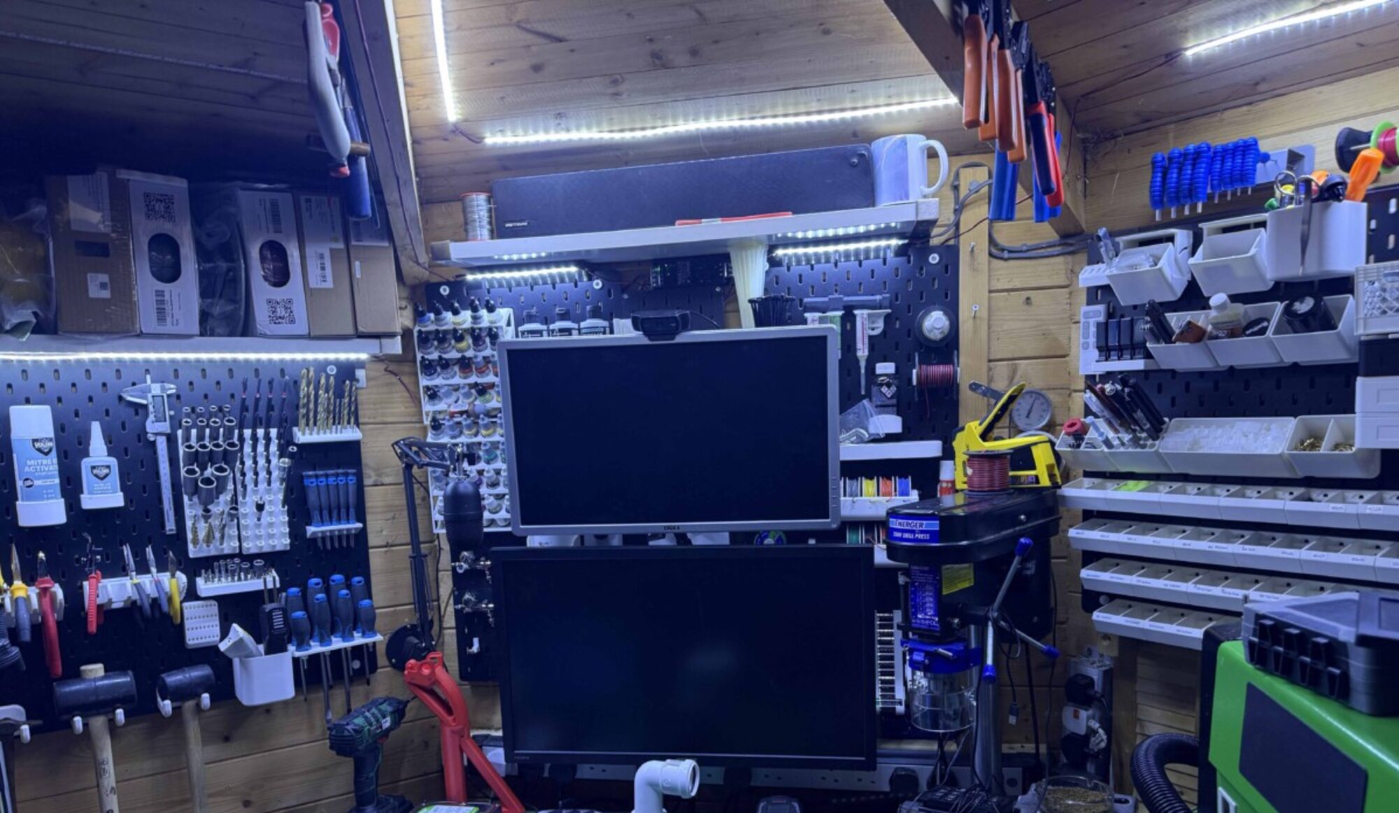
So as I wait on components from china for the cave monster time to clean out the enclosure and add make some bits to make my china CNC machine great and teach myself some more about CNC.
the spoil board is where I got to last time before the crash. and was working on a custom dust shoe. then other projects took over so I’m now going to start to make more stuff on my machine. So this I blog of my progress. see the photo montage below.
Time to clean my machine
As the machine has been sitting for a year since I last switched it on.
Before I get started getting a feeling I am going to need to clean the cooler water for the CNC machine, Ok not terrible but needed a cleand as organic material in the bucket. out with the old and time to clean the bucket fill it with some a 50/50 mix so 5L anti-freeze and 5L of deionised water as then bucket should keep it nice and clean going forward. now to pump it through the system see the pink in pipes and check for leaks, no leaks.
Now I have a clean machine I now to set it all back up. so over to the pc well remote link to the pc as it’s cold outside. so installed a remote desktop on the cave computer and have the machine running as the control box is on.
The Setup
Now to find my note as need to revisit them and get all the settings plummed back in.
Have installed mach3 need to install a plugin for the control board and MPG luckily have saved all this all in my dropbox so just drag and drop it all into my mach3 folder.
next up remembering pin set up so port 3 pin 1 = estop pin 2 = home switch pin 3 = limit switch and pin 4 = probe plate. so into inputs check there all right and enabled they are.
following the Chinglish guide, I go through the motor tuning and select all the right bits.
Config menu ports/pins
make sure all motor axis are selected
Next select input signals copy below
as i have added home and limit swtiches this is off wha the manual said now scroll down and enable estop and prob.all done
Now over to output signals tab.
now to click ok
Motor tuning for x y x follow below
now for A and splindle
now spindle
dont for get to hit save Axis settings after each change.
now one thing i forgot to set limits and homing that will mean your homing in revirse so on x and y dont forget to home Negtive only on x and y and your golden i have also set up the soft limits to prevent from crashing.
now to home the machine hmm it all z homes right x and y
adding edge finding and z zeroing tools scripts I highly recommend checking out
The legend that is Charlie Sarsfield followed his instructions on adding limit and home switches and his tool zeroing and edge finding scripts and install them
and now to make sure the machine spins and does what it’s meant to all works fine will be adding a new calibration plate so will test the scripts work like a charm
So the machine is back to working but me being me time to modify it some more.
Upgrading dust extraction system
before I start running some projects I am going to revisit the dust extraction as it’s okay just not brilliant lots of leeks for dust. so I’m going to make this modular and dust-tight hopefully I have added some fins to my dust shoe so it should suck all the dust-up am also adding parts so that vacuum tubing that will go through a flang that I can plug my shop vacuum in and out of. so over to fusion 360 to model the flange.
outer flange
now to test fit that before I make the inner flange. well it sorts of works i forgot to attach the inner tube so is floating so now making 2 outer tubes one so made them box the 35,2mm inner and then made so it will fit over the centre tube then enlarged it out to 36.5 mm with a 45mm outer
intenal section for hose attachementenclosuer external input
as for the tube end, I have made an inner opening end for 39.5mm and the flange end made it 35.2mm have then glued them to the flange. and screwed it to the enclosure. I forgot to take pictures doh here it is partly assembled with a vacuum hose attached from the vacuum end.
Have 3d printed a nozzle for the 40mm vacuum tube that I have a 5m length that i brought previously so I could extend the hose for the shop vacuum. I found a design some time ago and had test fitted it so I have cut down some vacuum hoses for the internals of the enclosure now going to print some clips to secure the hose internally to the roof of the enclosure.
all plummed in have ordered a new dust shoe from that has arrived fits well got to make adapter tube up infusion nothing flashy inlet side is 38.5mm and output of 36mm
quick sketch
2hrs later and it fits like a glove just need to trim down the hose lenth and install clamp
as now can plug the shop vac in and out. I might upgrade that too as is not too powerful think that will be next month’s shop if I feel it needs it.
Clamps
First up I needed clamping arms as I had a few issues with the tape method that everyone raves about. i might revisit this
so found some CNC clamps that I saw teaching tech use on a video so going to give them ago I will also test out some style ones as well as I need different ways of clamping down materials.
So new untested eSun PETG filament loaded into neon orange and away we go will check seems to be laying down fine layer 5 and only a little mess on the bed will check back later.
work fine now to re set up the machine
have now printed 3 diffrent styles will be testing them all out once I have the machine up and running. as we have some nice weather coming over the next few weeks willl get some diffrent materials as well.
3 different clamp types
I will be testing them all out I have a feeling the big one in the middle is too big for my hobby CNC machine.
have also designed my own one as well will do seprate post on that as this is already gone from being a quick post to entertaing me to another
Zeroing tool upgrade
Next up going to change my zeroing tool for a new one I have purchased off eBay.
new zeroing platedesigned to sit on corners and give true zero
as I was clever and used the power connector just need to unplug the old one and swap the wiring over now. All done and the magnet works well no hassle of crocodile clips well worth the £30
now back to the automated edge finder and tool z hight scrips now I know the XY thickness is 10mm and the z is thickness is 12mm so need to change the variables as shown below.
you will need to do this for all 4 scripsZ script
time to test the system
test complete have moved the plate off material and hit go to zero not bad going it a little off I didn’t set the tool diameter so that might be the reason it’s away from the corner.
Setting up Chinese CNC with fusion 360
Now I could do this using a different method as having used other CNC design software in the past and still have access to it but me being me decided I would go another route as keen to learn more about fusion as it is more than just 3d modelling tool.
So time to put some scrap wood in and see how we go, going to start with something simple as I am going to use my go-to program for design to try the manufacturing side of the program that I have no experience with so going to make a pocket in some wood with a simple part to see how it works.
as with anything design related i need to take some measurements so i am going to start by measuring my scrap of pine in the machine, I make it 200mm x 200 mm x 12mm then made a note of this so when it gets to it the program will know how big the piece is. i am going to machine is.
Next, i will need to make a list of tools as all the sample tools are developed for big milling machines with quick-change collets one day when I have a big workshop I will get a bigger machine. but for the time being, mine is only 3040 well actually it’s less than that more like a 3727.
time to gather some data for tools so I have ordered a set of six tools from china and with that i have the following data. so going to add them to the system along with some end mills and facing tools that I have in my collection.
incoming bits from china
I have also found prior information on some other bits I ordered in the past so been collecting them in a file to add as well.
will need to add these as well
The tool adding can be found in utilities under tool management
Click library then click the plus icon you will be greeted with a tool selection screen
you will be greeted with a tool selection screen screen
so in this case will be adding a 6mm end mill so I select the end mill.
Time to give the tool some description vendor name as I don’t have a link or id won’t add them.
tool i am adding
No to add cutter detail so I have this information on the tool
all the information added
I have copied speeds from another package as the default 5000 speed on the tool was mega slow. so have now upped it to 16000 and have calculated a minim feed rate 17.882 meters per min now running it 650 feed rate as 18 was way slow for wood.
now hit ok as don’t have a holder template for the depth of tool 0 as I don’t think it’s necessary as will zero tool after each tool changes this is more for an auto-loading tool machine perspective.
tool set up complete
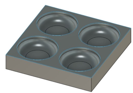
So infusion I have made this test part nothing special just make some pockets and will do more if it works this is a stage of learning so let’s see how it goes.
test part is not needed for anything just a quick sketch to see if it works
Now to switch from design to manufacturing add the tools then let’s see what they do.
manufacturing mode
Now for the set up this did seem a little daunting in the beginning think I have figured it all out I am going to only use one tool as this is experimental.
Click the setup button I am first going to move the origin from the centre to the front of the design is the same as the stock size it’s easy just click the dot on the front. as show below
Origen now front of the pice.
now the stock tab I have changed the stock to be relative to the box with no offset.
The dimensions from earlier 200 x 200 x 12 and the stock match perfectly
Next to the program number and comment.
just added a comment and then press ok
now we have this set up I am programming in a 6mm end mill so adding to the tool library.
so have programmed this six mm end mill in as the quickest one to add
first up going to perform this in 2 processes first am going to be pocketing the selected areas in the design then I will boar out the corner holes.
so to start going to the 2d pocket will then set the tool as my 6mm endmill. I will then select the 5 areas that I need to pocket out. click ok next under the 2d tool panel i selected the boar function with a 6mm tool selected each hole all 4 of them. selected ok.
I have run the simulation and it all looks like a good time to test it.
time to test it.
Time to post-process it then load it to the machine. and zero tools find the edges and we should be good to go.
The file generated not sure if mach3 accepts that but let’s have a look
Ok, the .tap isn’t recognised as a file in mach3 but I duplicated the file and changed the extension to .gcode will now load this into mach3 and see what it spits out.
loaded as you can see thinks the part is top left corner need to zero the tool to material height and find the edges using the zeroing tool and edge finder.
right zeroed the tool correctly and fount the edges got to love the auto edge and z finder. as you can see the image has been generated to fit the stock
right that’s worked will run the test programme and see what happens to wish me luck. Ok, that failed as it went in the wrong direction. I think the Origen is reversed going to change that in Fusion 360 then try again.
ok, I am a tit missed out on something from setting up in the homing limits in mach3 doh so I needed to tick 2 boxes. now homes correctly. as I am here also going to set up some soft limits so this all works right.
Away we go slow but steady think I need to mess with the speed and feed as it’s in and going down yay and the clamping just failed.
fist cutfaild clamps let go
As I have caught covid again in bed writing this so have had some time to reflect on the failure of the first run. back into fusion 360
go tool management and time to set some parameters so Spindel speed upping to 16000 and 650 meters per min feed rate I have also added multiple depths so it will now not go down 18 mm and try cutting out so now have set it to 5mm per pass switched to 2D adptive clearing.
let’s try running this test program recalculated with new clamps fingers crossed, going to use the same blank as woods not cheap and being pine won’t kill me on the dust.
first, to zero all parameters so out with the new zero tools and find the edges going to jog the too over the zero probes I have a magnet connected to the tool then on mach3 hit tool zero. the probe will go down and touch the plate touch and retract then go to jog x side of the tool and go to offset screen and hit auto x will move to the x-axis side of the tool and retract repeat on Y size using auto Y same will happen tool will move to the tool and retract system all zeroed now to remove tool and magnet off a bit. hit zero and the tool will be sitting just above the bottom left front.
z zeroedx&y axis zeroedready to run
Now to start the program away we go.
working but feed rates way off so going to update .
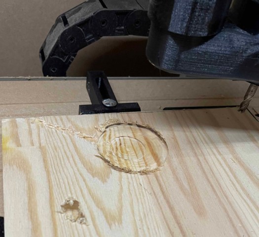
so back in to fusion as my gcoding days are long time ago so i am letting the program do the legwork. as you can see scraps had some battle wonunds not to self dont go to zero all when tool is down in the wood hoping it will be machined over have stopped the job. time to restart it. as the rate it was running would have taken a long time machine. now upped feeds from 18 to 650 mm/min so will now run the final 4 pocket first one turned out well.
faster feed and we are finaly making dustafter a hoover a little tearout but mimal
so have removed one pocket out of the design i think will run some other processes on this modle as i go but will attach the dust shoe as well as could feel dust in the air. but think i am going to leave that for another post as this has dragged on all week.
Now that I have figured out the basics I want to try running some projects carving from an STL file. making a 2d PCB and then using a bit to drill make the holes and engraving tools to make the tracks on single and double-sided copper PCB board, make some complex parts out of aluminium and more. these will be broken into different learning posts as don’t want to bog down this blog so will be another post as I learn more about both the software and machine.
Parts Incoming just had a bumper instalment of bits. so will be a post about this soon as want to make this a quick to set up stable.
In this case, I have 50 wooden yoyos I will be customizing. so I needed to make a jig for doing 4 at a time as I have 6months to complete this job for my boy’s birthday.
so first up I have my yoyo. so out with flang tool and callipers
in this case, I have used this to make a jig to hold 4 wooden yoyos so in this case, I used my callipers to measure the radius of the yoyo height and then used the fillet gauge to work out the curved radius on the edge of the yoyos 11mm then using
So over to light burn as this is where all the engraving magic going to happen drew a rectangle 120x120mm drew a circle 52.5m then using the array tool made 4 circles I grouped them then centred them in the rectangle. now to save this file will come back later to use it for the job. will export the file as a .dfx
ready for export
Now to open fusion 360 to import the dfx into it. as I want things to match between the 2 files. now that I have my 2d sketch in fusion. time to extrude the base by 22mm I will then flip it and cut it to the base by 18mm with 4 pockets I then added the fillet tool using 11mm and ready to print.
Jig ready for a test print.
ok now to slice it and print it.
time to print.
now back over to light burn to finalise the jig. I have measured the inner dim of the yoyo to 41.32mm ruffly i am going to size the centre at 40mm across. so will draw a circle in the centre of each circle this is my outer engrave marker.
Now to make some trim lines as going to make a cutoff board with a cutout for the jig. as shown below will make a 120mm hole for jig and also cut the bard size down in size hopefully.
so the red line is the cut line the teal lines are frames so just show and don’t cut just marker.
after the initial cut, I will turn all red lines into frame lines
jig board is now made this will be placed on the laser bed at the beginning of running a job.
fixing is now printed I could of run this using my CNC machine to make it in a fraction of the time part but printed instead as my CNC machine needs to be set up as i had a drive crap out on me so lost all settings. that is for another time.
now to use it on my machine but first, a test fit wow like a glove. just got to finalise the design for my son’s birthday party.
will do some engraving next in the machine. all set up will do a test run soon and up date this post
the cut out for the jigThe jig fits well ready for test run
test run done just simple engraving on one to see how it works before I run more.
Dead center logo too small for detailMy son will love it though
well, this was a bit of fun for the 2-day quick project more to follow as love putting out these quick easy projects.
here’s is a list of tools I have printed and have found useful to help make create and fix issues in my workshop. these are all things I have tested and used in my workshop some have been featured by others but hay this is my definitive guide to what i am using in my workshop at the moment.
this is a must for workshops that have lots of small parts that they need to put in small draws. this is my go-to tool when I get boxes of screws in to sort into their draw project.
nice quick 1hr 32 to print nice and compact to store.
3. Airbrush Wall Mount Holder with Drip Trays & Anti-Tilt by cncartist file can be found here.
in my very small workshop means my airbrush is easy to access off this handy little wall mount.
4. Screwdriver bit wall mount by SaKes file can be found here
use this and its remixes for drill bits and all my quick release bits.
As you can see I have a whole collection of bits easy to access with these wall mounts.
5. Spray can wall mount by Isalvador file can be found here
great for clearing some more spaces off my shelves for more kit and tools got 8 cans mounted behind the cave monster might add more. as a nice quick print, any wall space is a game changer for extra space have since got carried away and done both sides of the racking.
6.Disposable Glove Holderby mkelly file can be found here
12h48 print but saved me around £15 buying one off amazon.
Been meaning to buy a glove holder to mount on the workshop wall, As I have a box of nirol gloves kicking round workshop covid/resin work/ resin printing etc and I found this box so 1 money was saved for the next creation.
Metric Screw Hex Nut byJigby HDRI file can be found here
was a little slap hand with the pen highlighting number works well.
Love this great for determining what size that bolt you need is within seconds just used this as had a screw was too long by 10 mm so placed it in the guide figured out it was a 40mm bolt and I needed 30mm also identified it was an m5 bolt I required. one for my small tools tray. great for sorting that box of mixed bolts I have kicking around.
Wall-mounted spanner holder8 pcs by DaFed file can be found here
more saving spaces in draws as every spare wall space is used in my workshop as it’s so small. found this the other week love it went for the 8pces version as just needed to clear some space from my toolbox and this worked for me.
there are more bits I’m currently printing and testing which I will add to this list in the near future
you will need a licence for fusion 360 I have a free hobby licence that is limited but till i get time to learn the cam side of the program it’s free to me unless Autodesk feels kind and wants to give me a licence. not that they will read this anyhow.
open up fusion 360
the file I am going to remix is this spray can holder.
Now to remix it or in this case, I am going to create 2 bars for aligning it on the wall by using its original parts as a template. over to fusion
then go to insert drop-down insert mesh
you then can position it how you want i this case will keep it as it is so select ok,
now press s on your keyboard then type mesh you will select convert mesh.
Now select the stl
then hit ok on defaults as all other options only in paid verison.
sketch will now look like this
at this point you can simplify the sketch and make it fewer polygons by selecting segments and removing them hitting delete as shown below
selected poligondeleated smooths up shapepartly cleaned
So why do this well on flat surfaces makes it easier to select planes.
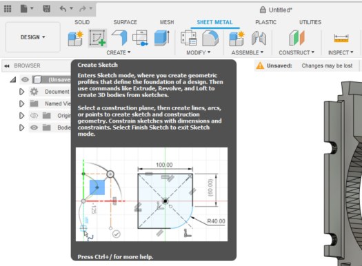
go to the sheet metal tab select Create Sketch, you are now going to select face to edit.
select highlighted plane and click you will now see it like below.
I am going to start off making a bar so i am going to hit L on the keyboard and will give me a line command.
as I am using snap to have determined the endpoint where I want to start the line click mouse to start the line
I next go to the bottom right corner of where I want the box i am making to be this will give me a guideline.
like below can now draw the 2 lines needed
close the shape
Now hit enter.
so that is literally the only bit i need for my idea but actually going to 2 as I want the top and bottom lugs to make int to alignment bars. so going to repeat this process and then we will continue.
I am now going to remove the original part from the system as i have the 2 elements i require for the alignment bars as will be easier than removing all the material I don’t need.
then hit del and sketch will remain
now to extrude it on both parts 100mm as think it’s a good size so hit E on the keyboard when selected object
hit enter and repeat on the bottom section of the file now change view please not i have moved them together for illistations.
Now to make the parts you now want to go to utilities tab select make
select the parts and in chose options as 2 body will need to do this twice.
this next part is as I have set my Prusa slicer to open when I make them so at this point you could save them as stl
now the part is in my slicer i am going to set it up for print by changing position before i save it out as an stl.
first to make it flat to the bed i will use the place on face tool F for a quick keyboard cheat
will select the bottom face
part ready to print in this case going to save it as a stl.
click the part then right-click and select Export as STL
save and parts done. then added them to one file ready to print will show more detailed remixes soon
then its over to the printer via octoprint in my case and away it goes as i have doubled up the parts as to racks going on the wall will take 2hrs to print.
parts all done ready for a test fit.
perfect fit love now to glue them all in place.
can find my files here do love a quick 1 day project parts are in to finish off the cr-10 so that should be up soon.
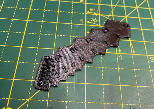
So my sons harry potter mad and wanted to dress as harry potter for world book day, long of the short we had lost his harry potter glasses.
So being the creative type and someone who loves to recycle designs I found an old harry potter prop I had designed for photos and decided to make some wooden prop glasses.
my original design
I then made the first pair of glasses up by removing the outer cut line and then using a square and weld tool I added some more girth to opposite end of the glasses offset the outer edge by 3mm and then notched it using the vector path edit tool to add 2 reference points and then converted notch to a path. then matched the outer edge of the glasses and made 10 x 100 mm rectangle as I had done a ruff measure of my son’s head. to the top edge, I used a circle tool to make a circle in the top edge of the rectangle then off set it inward by 10 mm to make the downward curve for behind the ear I then added a 10mm square to add some length circle to round off the bottom of the arms using path editor joined all 4 parts together and removed all bits I didn’t need. thin I did an offset inwards and set it to fill. then did a 3 x 5mm rectangle and placed in to cut path and i used the convert to path tool and inserted it in to the path. time for the first cut of the design. forgot to capture the screen of the original design doh.
fist draftworks wellNow to for a test subject
it worked but was loose as can be on my son so went back in a remixed it a little by shrinking size by 20mm on the arms and smoothing all sharp edges I also made a bridge by using path editor and adding a curve in the middle top and bottom.
design all done.
back to cutting now fits perfectly one happy boy who had it on all day,
time to cut v2cut out fine time to glueold Vs newone happy boy
A nice quick one. love the joy of making my boy happy.
this has been a bigger build than I first expected around 100 hrs of printing a lot of remixing was involved so some things worked some things I have had to print again and again till correct. think they are all correct now as they fit for me.
As will any project files they are a work in progress. still need to reprint final fixes to test but the current design work with some drilling or being an angel so no rush for me. i would say there are a good few days of printing involved with this project. but well worth it.
So what this part covers:
All in one Cr-10 Remixed for Dual Y-Axis linear rails kit
UPS 12v big tree tech
Filament runout sensor big tree tech
Modifing TFT screen firmware.
Dragon Hotend and issue correction
BISQU Flexplate
All in one Cr-10 Remixed for Dual Y-Axis linear rails kit
This is a remix of this design by Cornely_Cool can find the original design here. you will need these files for some of the builds my remix replaces the front-rear panels front left panel and several of the base plate files. this is a work in progress it works for me as of me writing this blog post.
So why am I doing this the original printed mod I built-in part 3 or 4 doesn’t work with the upgraded linear rails so It doesn’t fit so going to make something using an existing design with a remixed twist as its not 100 % right for me due to the dual linear rails and the design wasn’t using SSR and some other bits. First up going to salvage parts and order up some metal work going to raise the machine 60mm and have another 70 hrs of printing ahead of me first up parts. needed some aluminium 2020 and 2040 some connectors to hold it all together some corner plates and some new rubber feet as I disposed of my original feet from my cr10 also have hight clearance is an issue with a shed roof. might still need to lower racking. have also ordered a small 5v 3amp PSU to internally power the pi that’s running the printer. as this is a custom build have also ordered some aviation plugs to tidy up the wiring and install better-suited wiring. I will have a sonsoff switch as master power on and off and use relays to turn on and off power and lights for web camera. I will publish a full shopping list. end of the post when I have calculated what I used and what you will need. will add build of material
Time to start the remix so starting with the base panels going to remix the Mosfet panel as don’t use one as running a silicon heat bed. so will house SSR relay, a 2 channel 5v relay for lights and printer and UPS board if and when it all shows up.
this is done using the panel as a reference and using PCB footprint diagrams have added a 6mm standoff for each part.
will house SSR UPS and 2 channel 5v relay it a work in progress relay fits just only screws fit
Next up I am going to remix the raspberry pi and pi PSU plate as I am going to use a hard-wired PSU 5v 3A so will need to make some mount holes for the PSU but first going to test its powerful enough. as I don’t have a reference diagram going to photograph the underside of the PSU and measure it using it as a reference image. will then trace holes for mount. won’t print it till I have tested PSU. have made some air vents and bars so i can make holes to mount it when it’s done.
the PSU holes are off as on the wrong side but will drill and bolt PSU in place. The final file changed but might be off.
The final modification is to the mainboard fixing plate so used the existing plate as a reference for size then added footprint overlay to trace holes for mounts.
insterted image of board set to size as reffrenceadded standoffs on over layexstruded finlal plate for prinnting
the final hurdle was going to print the massive PSU plate on the cave monster cr-10 but due to wiring snagging I cannot print on it so into Prusa slicer have cut it in 2 will print half and half on both the Prusa so I can do it in half the time will line up and glue the halves together.
love the cut functionas i have the print farm up and running i will print half one both the printers so saving time.
Now that I have remixed all required base plates now I am going to centre the middle post I have remixed the font panels to be blank as due to the dual linear kit I cannot fit a front-mounted screen. so going to remake the panels to smaller and more central with a 5mm notch to allow for fixing plates.
Gone for a central notch 5mm deep changed it again since this maid it longer.
Next, up is the power plug panel got to notch this and move the power connector as it’s right in the way of the plate.
slotted for brackets with 5 mm and move power connector by 20mm to the right changed it again as just on the borderline.slotted by 5mm ready to print.The last plate finishes just base plated to finalise. just had to add a hole for cables for the screen
The last panel was modified for screen cables for mounting to the frame.
Time to start printing I am going to run it all in PETG. time for some overnight parts I am going to set my Prusa’s going shame I haven’t reinstalled Octofarm to run this but will do on the next build as will be running 3 printers in it. About 4 days in now all printed apart from pi and PSU mount that’s currently running and some fixing brackets. time to build the base has been tweaked the construction of the metalwork with some extra brackets to make sure this going to the stable with the printer on top of it.
last part on the prusa printing then to assemble it all.
Oh wait fan director last 8hr print that’s overnight parts for as I am already deep in assembly.
last print of base builds overnight parts.
Time to build it.
Time to put it all together for the final time hopefully and I can then put a pin on this machine.
first up assembled outer frame with base runners and corner plates with the feet i have brought. will bolt down the centre rail once I have centred it on the base plates.
metal works arreved atime to start putting togethercenter rail in time to bolt it togetherand im out of 10mm blots damit.
now I have a squared base I will add the uprights and bolt them down with the L brackets i have sanded the tabs on the printed walls so starting from 2040 I placed the first part I then added a bit of 2020 in the middle and continued on till all the walls was installed then using 2040 plates i bolted the base to the 2020 uprights. I will add another bracket on top of this to secure the printer to the base.
First panel is in. all the walls are fitted.
now on to the base panels, I will place them loose before I add the fixing clips in place.
fr dry fitting panels.all fits well.not 100% lining but will workjust going to change pi panel as psu wont let me fit the power connecot to pi.
all my components line up perfectly well almost but still bolts down sold just need to adjust the centres slightly as the footprint diagram I found is wrong on the relay. I am getting better with each project build. now everything is in place have added the clips have bolted down all the components apart from PSU as need to modify it for the upgraded fan.
fitted new PSU base plate but holes are off, needs to modify
Final version the pi & PSU plate is done holes are wrong but I just drilled new ones and screwed it down with some 6mm M3 bolts I will start wiring up tonight.
actually going to need cable management. so time to fire up the Prusa 1 more time for a plate of connectors.
the last print for the base.
The wiring
First up will run the mains wiring from the 3 pin kettle connector to the Sonoff switch then across the on/off switch for the pi PSU and the main printer PSU. now I have the main power in.
Main power all in forgotten my wifi password so I cannot test the Sonoff all fit perfectly.
Next, I will run negative connections for the 2 channel relay and link the relay to the pi so I can control it via Octoprint. I will then run the positive to the PSU and lights circuit for the web camera. next up are the jumpers from relay to the raspberry pi going to use 5v ground gpio 23 and 24 pins I am also going to use 3.3v and pin 9 ground and pin 14 for a temperature sensor inside the enclosure so I can adjust the fan if it gets too hot inside.
Ok, my worries about the mini PSU and voltage is fine there is no under-voltage which is great as sometimes things are not what they are advertised as.
time to pull out the wiring diagram for the mainboard.
list all connectors as you can see negative and positives are needed on end-stops and thermostats if not get kill alarm so on the end-stops and thermostats square is= to ground.
end stops and motor connecotrs are wired board side got to do some soldering but will cover that later as need to make some new wires for the heat bed and y-axis.
I am actually going to modify one of the front panels to house a Micro sd card reader and a fan speed controller PCB so back into fusion 360 going to add foot block and add 2 3mm holes to mount the front 2 PCB holes as then in the main plate I will add an 8mm hole for the potentiometer. then over the other side of the panel, I am going to cut a hole for the sd card reader to squeeze into I will then fix it with hot glue. as the original design used a USB switch to allow for firmware update the skr board only allows for MicroSD upgrade so as the board is going to be embedded this will allow for firmware upgrades in the future.. this will be a 4 hr print I think. as I test fitted the 2 halves I needed to reprint this anyway as it’s off by 10mm so now will fit perfectly under the front plate support
So out with the callipers, I go to make everything will fit and is sized correctly. time to modify the sketch.
will do an overnight prototype print. well, morning has come and yes everything fits fine just need to screw the PCB down and hot glue the sd card extension in place and we are a bit of sanding for the tabs and should be good to fit. note to self make sure you sand the tabs another 3 hrs print and will defently resand the front panel as snapped a tab these things happen when prototyping but its starting to take shape.
whilst I’m at it going to add 10mm space on the rear power panel as it was very tight prefer there is some wiggle space more airflow as well going print it on ultraviolet tonight back on with the assembly tomorrow.
redesigned as was too tight on the centre spacers.
All panels are now fitted going to cut myself an aviation plug holder jig. so out with a sheet of acrylic time to cut and bolt together.
So over to light burn a sheet of acrylic in the machine let make this design I got off Thingiverse https://www.thingiverse.com/thing:4201220. I have relayed it out slightly different as I want to fit on a sheet of 300×400. if someone wants it will share it.
as I want a good connection going to start with the 4 pins i have given up on the six-pin as NEMA wiring is too fragile.
ready to cut.
Not everything you find on Thingiverse is right so had to modify the file slightly to get it to work but now a more compact jig. as the dfx is segmented and didn’t cut right in light burn fixed now and modified the base as was too big for smaller workspace ready to solder tonight. got 1 socket to solder
assembled ready to make my new connectors
Nice and neet now for the heat bed connector need a new connection as the board is about 20cm further than it was originally also my bad soldering means it intermittently doesn’t work. so time for a fresh connector.
time to solder up a new heat bed connector with longer wires so I can wire direct to PSU and solid-state. out with my soldering iron I know the following
Pin 1 = Thermostat Positive if wired wrong alarm will sound on SKR board
Pin 2 = Thermostat Negative if wired wrong alarm will sound on SKR board.
Pin 3 = Heated Bed as 220vac voltage don’t matter which goes to witch
Pin 4 = Heated Bed as 220vac voltage don’t matter which goes to witch
2 down 2 to goready to instll
have put continuity meter across the pin and end of the cable and they all check fine
now to wire it all up and we should be good to test.
all ready just need to shorten the neo pixel cable as made it way too long. going to use the bit I chopped the neo pixel wire I will use for the filament run-out sensor cable. Then it’s time to finesse the cable management.
The next issue the fan direction vent is hitting the y axis so going to make my own custom offering so going to find the footprint of 120mm fans going to make it easier to fit low profile fan shrowd. should have space as gone for 35mm high to 19mm high
So should have good clearance space. 6hr print will run tonight need to swap filament as running low on Neon orange.
Done just need to see if it fitssd and fan controler fittedrear shot of it all.just isnt sitting right.new Fan air directonal. nice and compact but does buffer the air might modifiy it more in the future,
The wiring list is getting shorter just time consuming getting there.
end stop and motors temperature sensors and relay wiring left before I’m done.
Time to link the raspberry pi to the relay using 5v ground and pins gpio pins 23 and 24.
Temperature sensor installs time so using 3.3v ground and Gpio pin 14 for the probe have added the Dupont connectors to go over the gpio pins going to have to do some changes via rasp-config to let the system know pin 14 is sensor pin. but will check if this is needed or not as it is an old guide I read. I will also need to add a plugin so it will display the internal temperature of the enclosure so I can monitor and adjust the fan speed accordingly.
going to have to change the sensor type as this type I have installed does not have a pull-up resistor on it so just ordered another type off eBay so will swap it out.
Temprarture sensor installedJumped to the raspberry
Finally, The wiring is now all complete just need to test everything works.
finished all internal wires oh wait missed the lighting circuit Relay.
The camera light relay I have pre-made a cable from the 12v supply the positive will go to the power connector negative will go via the relay so I can switch camera lights on and off when a print starts and ends. have had a change in the design as I’m not using USB switch going to wire power connector to where the switch was going an install an A to A USB panel mount so I can connect the camera to pi externally power will be via the relay so I can turn halo on and off if required, should have parts Monday. as I wired the power socket tonight I had a thought about the USB connection wouldn’t work. back over to fusion 360
power for light rig is in.
Designed the first version it’s printing now but it’s not going to work as needs relief for the screws so have remixed it further and come up with this going to print it so have both options but think this is the winner.
v2 think this is the winner
As you can see from original to remix v1 and final v2 these are the things you have to take into account when remixing a project.
orignial version 1 and 2
In fact, I am going to redesign it again as the cable layout is different so back into fusion I go doing a scrapy print to see if it works but this should be the final design have made a few changes including screw head relife and it fits perfectly added to the remix pack
version 3 with cut out for plug that turned up
this project is pushing my design skill and I love it.
the finished item I do love playing around in 3D print.
Time to fit it all into the machine.
fitted like a gloveall wired in
Right, I am on the home straight I need to make some form of protection for the printer’s innards.
going to cut some black acrylic insert them in the middle of 2020 extrusion as dust covers.
so been thinking about how to do this without having to remove the front of the printer going to do some testing. I am going to cut some test bits 20 x 74 mm at a start to see if I can insert it then centre and add a fixing clip to hold it in place I will then make will also design a middle clip that can be removed to gain access. well,
that’s the idea, time to make some test bits. so over to light burn and as I have some offcut left from the jig build going to cut some strips to see what can be inserted,
time to cut some interest to test have labelled them for ease of use
So looking front on Left = 77 middle = 146 right = 75 now to make 2 x 200 long size X plates for each area will then 3D print the customizable design for centre plates then to design some clips that will be after I have the covers fitted.
I have decided to make it a 3d printable version obviously they will be subject to where your cross braces are. but you can customise them in the slicer. i am going to print my covers so they match the base as I could cheat but I want this to be a mostly printable design. also, put a clip together
the first plate is printing
here is the centre plate design will be making left 70mm, 138mm and right 68mm. the centre area 72mm across. total area 100mmFirst panel inone side done.
Clip design I have put these in to hold the panels in 3 per panel so 24 in total. currently printing a sheet.
final plates are printing on the printers should have all the dust covers done tonight then I am ready to assemble the 2 parts have hit one minor snag as the end stop bar is skimming the middle plate need to take a few mm off it to get it to work right will think about how I do this might just be a shorter screw and a 10mm off the tube with a hacksaw. No, I own a 3d printer. so now printing a shorter 11mm x 20mm tube and have a shorter screw to fix the issue.
only issue is the centre plate as the end stop bar is clipping it.
All fixed worked like a charm now does not rub on plates and makes contact with the endstop. all plates fitted made a cut out for dust cover so waring was more neat.
Dry fit works well.
dust covers all fitted and wiring from neo pixel hidden also hidden the filament sensor wiring if there’s any interest will publish all the other bits I found on Thingiverse that used to help with the project.
Yay parts from china
Just as I was about to put a pin in this build and post the post I have now received parts from aliexpress so back on to some more upgrades. lol so this will be tomorrow as one PCB to fit and wire and one sensor to attach. and a Flexi plate to stick and fit.
So a new day has dawn going to try wrapping this up today bar printing or tuning.
UPS big tree tech
This should be easy to install one 3 pin plug to the mainboard from the ups and 12v supply just got to figure out where to place the board in the enclosure I think I am going to make some holes and add some standoffs as I did with the 2 channel relay. need to look into firmware changes for its use will cover this at the end of this post.
My fingers are crossed my calculation for the footprint of the board is correct and this just pops in with some m3 screws. Well, I’m too good fits perfectly just got to finish wiring it up.
Make sure that the + & – are wired correctly as will destroy the PCB if wrong they are labelled on the bottom of the PCB then links them to the power input on the mainboard like shown below.
then insert the 3 pin connector and connect to pwr-det on the mainboard and then back to ups PCB and it’s all installed hardware-wise.
Now for firmware changes
There are 2 files you will need to change first is in the feature folder look for powerloss.h
I have changed debut and saved each cmd this will save the last state on the printer if there is a loss of power now over to the Configuration_adv.h search for POWER_LOSS
then uncomment the above this is set up for my printer mainboard so pin number might need changing on your device. and purge and retract might need changing as well.
will compile this after making other changes for the filament runout sensor
Filament runout sensor big tree tech
As I waiting for this to arrive seller sending another one middle of February so instead of moping around the workshop getting ready for it all to arrive.
Ok have found a bracket on Thingiverse I am going to remix it so I can mount the bracket directly to my 2020 so will be adding 2 tabs in Fusion 360 so I make this a reality. first, I am going to import the mesh in and will draw two rectangles using the top face of the bracket I then extruded them by 4.40mm then made a centerline in a sketch and added matching holes time to print
Quick and dirty modification but will work.
I will print it shortly the spikes will print not sure why they ended up there are joys of modifying a mesh
Just waiting on the current print to finish should relay run the farm but need to get neon orange up and running it’s on my list of things to do. it’s a long list as always.
Printed ready to fit when I get the parts. just test fitted will just what I wanted.
works on 2020 fine.
As I now have the parts time to fit it all to the frame for real as the sensor has arrived.
hidden all the wiring in the frame with some clips.
Going to connect it to the mainboard E0-STOP port you will have to switch it on in the firmware pin 15 was already selected for filament runout.
Now you will need to turn it on in firmware so in configutation.h
find the following FILAMENT_RUNOUT_SENSOR and uncomment it like below.
Next, scroll down and uncomment the following FILAMENT_MOTION_SENSOR and FILAMENT_RUNOUT_DISTNCE_MM set it to 7
and with that just need to reflash with v5 of the mancave monster firmware on the mainboard and we should be good to go.
My Current Firmware CR-10 BTT E3 mini 2.0 with BTT UPS, BTT Filament runout sensor, BL touch and Neo Pixel 18 pixels installed compiled here if you want the vs code files ask and will happily link it for you.
all components are now installed going to join the 2 printer halves and running initial tests. fingers crossed before I permanently bolt them together. Wiring issue, not a big one negative on neo pixel is the wrong way around not a biggie just taken a photo of the pins.
Mine was the wrong way around so out with crimp tools and time to make it right.
remade the connection so let’s test it again. now seems to all be working.
Homes check bl touch works check hot end heats not working for heat bed erm ok not heating need to check the wiring.
Got a feeling negative is what I meant to pass through the SSR going to go back through my notes.
Was 2 issues had heat bed plugged into the extruder and hot end in the bed and the negative was positive no damage all fires up now and works
Just print the front left panel with a modified hole for screen cables. so going to leave that running overnight, just fitted and perfect so that’s finalised.
One thing i will need to revisit is the relay board but I think that will be done in the future as projects are already way overrun and used lots of PETG I really need to invest in centre callipers they are uber expensive one day shall order some.
Time to modifiy my racking
The next job is lowering the racking so I can fit the new printer on the shelf need to move the spool holders down and then drop the shelf level down by 15 cm approx.
cleared the shelf and now to focus on removing shelf and old wiring as will rehouse the wall-mounted pi down also binning cheep fans as they temperature should never get that great and the nose one of them I producing is bad.
spool too lowspool not high enoughJust rigjht
Have managed to drop shelf approx 120 mm have refitted shelf and refitted Prusa’s have moved my pi off the wall and disconnected fan. I shall monitor CPU temp via the plugin.
space is ready for the new printer
Now to place the printer in its place well nearly first flash the firmware and cave monster ready for action well nearly as I want to finish off the mods before I set it in place.
TFT Screen firmware configuration
One final tweak I wanna look at is the firmware for the screen as want to disable a few features and rename some descriptions if I can not sure it’s possible. but by the power of google.
first up looking at the config.ini
In order for the TFT, firmware is able to provide all of its functionalities/features, ensure that the following options are enabled in Marlin firmware.
General options:
EEPROM_SETTINGS (in Configuration.h)
BABYSTEPPING (in Configuration_adv.h)
AUTO_REPORT_TEMPERATURES (in Configuration_adv.h)
AUTO_REPORT_POSITION (in Configuration_adv.h)
M115_GEOMETRY_REPORT (in Configuration_adv.h)
M114_DETAIL (in Configuration_adv.h)
REPORT_FAN_CHANGE (in Configuration_adv.h)
Options to support printing from onboard SD:
SDSUPPORT (in Configuration.h)
LONG_FILENAME_HOST_SUPPORT (in Configuration_adv.h)
AUTO_REPORT_SD_STATUS (in Configuration_adv.h)
SDCARD_CONNECTION ONBOARD (in Configuration_adv.h)
Options to support dialogue with host:
EMERGENCY_PARSER (in Configuration_adv.h)
SERIAL_FLOAT_PRECISION 4 (in Configuration_adv.h)
HOST_ACTION_COMMANDS (in Configuration_adv.h)
HOST_PROMPT_SUPPORT (in Configuration_adv.h)
Options to support M600 with host & (Un)Load menu:
Options to support dialogue with the host (as a prerequisite)
NOZZLE_PARK_FEATURE (in Configuration.h)
ADVANCED_PAUSE_FEATURE (in Configuration_adv.h)
PARK_HEAD_ON_PAUSE (in Configuration_adv.h)
FILAMENT_LOAD_UNLOAD_GCODES (in Configuration_adv.h)
Options to fully support the Bed Leveling menu:
Z_MIN_PROBE_REPEATABILITY_TEST (in Configuration.h)
G26_MESH_VALIDATION (in Configuration.h)
I didn’t use this as couldn’t get to compile I will revisit this
Z_STEPPER_AUTO_ALIGN (in Configuration_adv.h)
so that’s the merlin firmware now done not to look at the config.ini.
custom logo
cave monster
so lots of settings and functions here have changed a handful of colours and the way it talks to octoprint.
next up going to look at the actual firmware pre-compiled so I can see what changes can be made. that will be a separate blog post I have added a new icon set and flashed the screen with new firmware to see if it helps.
Dragon Hotend and issue correction
K decided I would go the full whole hog and upgrade the hot end as well. as I wanna look at the movement in the x carriage on the extruder bracket. I also why it is quite tight on the belt.
Issue 1
I fixed it was the hole the direct-drive bracket is bigger than the m5 to linear rail bolt hole so have used 2 countersunk screws to centre the bracket. works well,
Issue 1 FixedNew hot end fittedexstruder reassembeled
Fitted the dragon
I have removed the old OEM hot end. 2 screws and that’s gone now to fit the dragon hot end using Capricorn petg tube between it and the direct drive all fitted now to put the hot end back together upgrade is done. but not quite right cannot get filament into hot end tubes not quite long enough so time to order a length of it so I can get this right.
Issue 2
I noticed there is a lot of friction on the belt so I am going to swap the pully end around as I want this to be smooth and can align the pully across the beam. 4 front screws removed. pully off and rotated now to put the machine back together much smoother think I have fixed it might need a slight tweak but let home the machine and see what happens.
just going to make a benchy test. before I fit the new flexplate.
running into issues with filament sensor the hot end now clogged got a feeling the Capricorn tubes melted so I am going to strip down the hot end tonight and have a look and see if it’s down to that as removed nozzle and still cannot get the filament to come through. have ordered a back up hot end the big tree tech v6 hot end and a fixing bracket as a backup as got a feeling this isn’t right.
will disable the runout sensor for the calibration as I have a feeling it’s thinking it’s a clog on the hot end even though there is now a clog.
removed hot and cleaned and the issue blockage in the tube put it back together loaded it ran 20mm through it and bam blocked again so might be my filaments shit or the tolerances of the tube is too tight might try a different batch and see if I get any joy other wire going to revert back to my back up but that’s going to delay first print. by 3 weeks but going to launch this part of the build and then come back when it’s all printing right. at least makes me know that the runout sensor working. so will re-enable it after I have a calibrated machine.
going to first install the flex plate whilst i figure this out.
BISQU Flexplate
This is something I love on my Prusa printers will hopefully be the same experience. so to install going to need to stick the magnetic sticker to the glass bed.
so have turned over the glass sheet and cleaned it using isopropyl now to apply the sticker sheet went down will not be 100% straight but no one will notice.
Time to cleanSticker fittedAll installedAnother anglejust need a working hotend and good to test
before I test the plate on top. going start by resetting the EEPROM and then going through calibration again as don’t want to mess the sheet up. but that will be in part 7
all fitted now a waiting game for the new hot end so will leave this here final part will be testing it all out.
A happy New year to you all, Incoming parts have arrived so time to finish off this project last 6 upgrades firmware recompile and hopefully will be all done.
Yay The kit arrived when I was away so a bag of bolts and t-nuts aluminium end plates and base plates.
this is going to evolve some guesswork as with all china kits they never provide any instructions but basically will fit the 2 cross braces and add the rails to both and bolt them down will leave the supports lose so I can make sure all is plumb and attached the bed this is in theory fingers crossed.
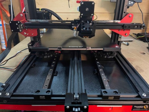
Wow, they are tight going to loosen the frame ok now to centre them as best as I can. Now that I have the 2 cross members installed loosely to add the linear rails and 18 nuts and bolts on each rail to bolt them down lining them on the cross brace.
Now to mount the bed to the rails start with one side front bottom placing aluminium spacer and 30mm bot I fix in place I can see the left is off so nudge them to line up so I can put a bolt now to install the remaining 14 spacers and nuts. bed or carriage is attached I check it for lateral movement nice and smooth so I reattach the belts and repeat can that the top needs to come over. now I have it centred time to tighten everything up oh then looked at reference images of add noticed as i had 3 bits left that i couldn’t identify.
They are to make contact with the end stop. so add them now to install the rail end plates so another 8 screws and t-nuts. 4 aluminium covers later it’s done
Now waiting on spacers for the bed as I manage to lose once so should have them Friday also chatting with the vendor as my big tree tech package has gone missing in my absence. below is a montage of what happened through the build.
Lets get startedfixing platelinear rails.bot cross sextions fitted18 t-nuts per rail yay menow to the other side.all bolted down now to fit the bed10 spacer and bolts installed 6 to go.can see the belt is off time to nudge it.nice and straight added end stops
Neopixel install
Bit of 3d printing have found a led tape mount that I have modified to fit the gantry perfectly I am currently printing the bars in 2 parts will then print the end caps. 3 hrs later will just do a test fit tonight. ok, the first attempt failed so going to print into parts and have gone for a solid infill to reduce the movements see how it turns out. the bit that did print fitted though.
failed again argh going to look at slowing the print down to see if I can get it to complete
attempt number 3 with a raft this time let’s see if these thin columns will print.
So added a raft fingers crossed. Update 50% done still holding.
I miss calculated the length going to use a failure so sort it so chopping down a failure bit. also need to get a heat gun on it to take away the stringing.
made a mall 30mm section out failed parts and put 12v thought it to see if it lights and it did now to finish the cable.
lights up now to finish the cable.
right, this is going to be a bit of guesswork I will need to see how it pans out as I have changed my mind on how I am going to set it up but from what I can see I will need a 1000u competitor and 330k ohm resistor the competitor will go between ground and live and the resistor will go in line with data wire. I will make a 3 pin JST Xh connector so I can plug it into the mainboard this is the simple part. to install it I am going to stick the 18 LEDs to the top bar of the printer and stick it the v slot or I might stick it to some insert clips I have found that will allow me to stick it to it. still toying with this as I type this post. now the firmware is where I am going to start asking more questions as no one seems to be able to answer my questions. argh, have contacted support as they all seem to be for an earlier version of marlin firmware see what they come back with.
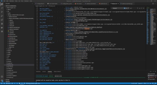
Figured I all out myself and was it a fucker so bugfix changes layout you will need to go ini folder in vs code fetures.ini and then change the following. go to adafruit comment on neopixle_led change to the following. NEOPIXEL_LED = https://github.com/CommandoreBombardiero/Adafruit_NeoPixel as shown below.
Now go configuration.h and search NEOPIXEL then change like below.
corrected code
Then build it will fail with something about the delay so then go find Adafuit_neopixle@src- some numbers and letters you will need to change the location in the brackets to the location of your delay.h file in marlin/hal/shared/delay.h can see it for my dropbox location below.
build it again might fail but then if you build one more time success, wow my mind is numb now only taken the best part of 3 weeks on and off to get this to compile now to make and add connectors and hopefully, it works.
Next, up now I have it compiling is to make up a 3 pin plug so looking at pinout i know i will need a 3 pin JST connector and 3 crimps and JST crimping tool this is fiddly could also be done with Dupont connectors if you didn’t have JST ones kicking around.
Time to update the firmware wish me luck. sd card in hand. a bit nervous lol.
hmm, not working I am not sure if it’s the wire or something else going to check through my notes and see if it’s something like the wrong controller pin or it’s tested the wiring and got a continuity check on negative and positive.
checked over the firmware code and had assigned the driver pin as 4 instead of PA8 will flash the firmware again v4 I change the version number each time I make changes to the code.
yay it workedback in the holdercable managment clips work well.
Now to put every thing back together and add some cable managment an figure out a way to mount the unit to botom of the printer well untill i figure out my next mod more on that in part 6. will also need to re calibrate the first layer again hoping for the last time.
Once dialed in going to start running parts for the next modifcation going to take a few weeks to get bits in from china and ooznest also got to rework some bits as well. going to do the rework first before spending out on parts. as all these mods hav spireled out of control.
Next steps
When the bits turn up from china I need to enable filament runout sensor and power loss in the firmware but that’s a lot more strait forward.
Will make changes to config.ini for the screen when get the new bits as will allow the main board and Octoprint to communicate with filament runout sensor as that’s where its plugged in.
We’ll all short lived control box don’t fit under machine to going to make something better see part 6


You must be logged in to post a comment.