Warning: Invalid Jetpack option name: edit_links_calypso_redirect in /home/u204111836/domains/joshsmancavelive.co.uk/public_html/wp-content/plugins/jetpack-protect/jetpack_vendor/automattic/jetpack-connection/legacy/class-jetpack-options.php on line 231
Warning: Invalid Jetpack option name: onboarding in /home/u204111836/domains/joshsmancavelive.co.uk/public_html/wp-content/plugins/jetpack-protect/jetpack_vendor/automattic/jetpack-connection/legacy/class-jetpack-options.php on line 231 josh – Page 4 – JOSH'S MANCAVE LIVE
When you know how to make 3d models and prototypes 3d printer is one of your biggest assets in the small workshop. this whole project took 4hrs 30mins to complete from idea to finished working design and 4hrs of this was the print time.
Back story
As I am currently waiting for virgin media to fix an issue with my router before I can make the new website live as need to port forward from the VR machine. So to make sure i can just start to work on projects I am re-laying out the workshop. I have had tools sticking out of dump bins as I didn’t have a space to place them it’s got a little out of control. so back to the problem at hand and the point of this post.
The issue
Bocsh Wireless glue gun never found a handy spot for it. so last night after pulling out my callipers for some ruff measurements. I decided to make a handy wall mount.
The MountDesign
So fired up fusion made a 40mm circle and extruded it to 55mm then added a new sketch and made a new circle 35mm at on end of the cylinder I then cut into the cylinder 30mm I then added a 5mm hole through the middle and then using a bevel tool made a cone to exit.
I then flipped the design on its side and made a 55mm x 30mm rectangle I then moved it from the central axis to the outer edge of the design and extruded it by 5mm I then added 2 countersunk holes. by using a circle tool and the bevel tool. Now to export it to print.
Now to drag it into Prusa slicer and slice away made this design so won’t require any supports of rafts to print. printed with 25% infill. gcode ready for upload to octoprint. Away we go overnight parts was a 4hr print left it going as having rigged up relays for the lights and power of my printers so once completed it will shut off.
The next morning– The result
As you can see worked flawlessly apart from me being overzealous with my talk driver screwing it to the wall. but it’s perfect for my requirement.
My next job is to add a keyboard draw to my workbench using the track system but need to go grab some bolts and 50mm x 50mm wood from the local hardware shop.
Wow, September already has lots going on back in London just doing a winter clean in the mancave. as has been come a bit of a junk pile as lots scrap around packaging and just too. tight on space. so I have been taking bits into storage or down to wales each time I drive down.
as want to do more with my CNC machine and get the print farm set up with my old cr-10 in the mix as well.
So changing configuration around in the shed. also having to rebuild my workshop computer as it died a death. I will be swapping over to the new site. just got to set up a host machine. get the new web server up and running. also going to redesign the site as was not 100% happy. so for the time will continue on here for time being.
But will be covering some repair blogs about fixing min temp on neon orange hoping it’ an easy fix do have a spare thermistor if worst-case scenario. I also think it’s time for octoprint rebuild and some cleaning of equipment and repositioning of the pi enclosures.
so long and short there will be some more content shortly. do that.
list of upcoming blogs
CR-10 can I fix this gremlin and get it printing the way I want as it’s been under my feet for a few months now. first up the heat bed going to replace the thermistor and see if that fixes the issue. if not will work will then upgrade the machine more to come on the mods later.
how to make workpieces jigs with a CNC machine. wife has been out buying gift ideas for Christmas so I want to be able to customise them with the laser. so going to design and cut a jig using a CNC machine. using fusion 360.
Making custom gifts with the laser and a bit of a walk around lightburn software. also going to get my rotary out and try some glass etching with the laser.
know I have been gone for some time been working on projects and other bits I am currently in wales I will be back at the man cave next week. the swap over to my creative space is coming just working on the new server my new service provider swap happen just before I left for holiday.
I will get the new server up and running on my return putting the arcade project on the back burner as will be all here in wales will take some images of the progress. shortly.
The new servers have been delayed and I will be getting a network and ip boost with virgin media business line going the joys of working from home please check out the new website as it where all my stuff is heading over to I will be shutting this site soon with a link page to my new site come check it out. http://joshs-creative-space.com/
New website has gone live i will be keeping this open for a week or so till my server arrives and then i will be forwarding it to the new site. for more greatness please go to http://joshs-creative-space.com/
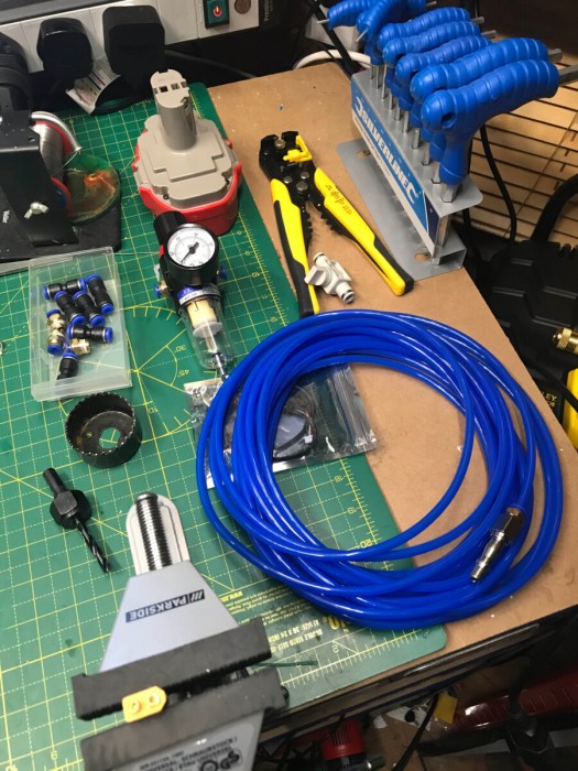
As my compressor is arriving today i have been clearing space to place it and have pre bought airline and compression fittings.
I will be splitting the compressor so it will run air tools as well as feeding my lasers air assist.
the compressor will be on its own power source .
50 mm gap all around wow it only just fit in the corner of the workshop.
the word of like a glove springs to mind well she is in and a beast, loud but like any compressor will fill it when I tomorrow and run shut off valve a second regulator with a water trap to solenoid to air assist.
tomorrow’s operation
A nice early start thanks to 3 years old today will fill the compressor with air and get the airline run so I can test the system out later. fills up in about 5 mins but is a tad noisy time will tell might need to look for something quiet in the future but for now, it’s fine.
right have run my airline in temporary to test it as ordering some more connectors to wire it the way I want it to work as will have dual lines in one for the standard pump and one for the compressor as its a noisy beast will not be able to run it at night.
tested it and it’s not working right I have a type B valve and need a type A speed restrictor valve. so have been kindly sent an inline valve to install to correct this so hoping tomorrow to get it running. thanks to the air assist group for help.
part received will be fitting later tonight with some more mods. as doing more than one project at a time.
I am also ordering the other bits I need so I can switch between the machine air pump and compressor.
all bits are now here going to test and document it
So 50L compressor with the regulator set at higher psi than needed to water trap regulator set to 25 psi then to Y spitter one feed compressed air other feed to aquarium pump single exit to the solenoid will use laser air switch to disable pump motor when not in use. I also have a on/off valve to turn off the compressed air when not in use.
In fact i have to run 2 on/off valves as when running one the electric pump hose popped off so will open one and shut the other when not in use.
I have now mounded the solenoid to the laser machine. I might also mount the regulator to the machine but for the moment I have wall mounted it.
bulkhead connectors installed to y splitter just need to cut and splice input line.
Have also removed the L connector from the laser head and replaced it with a straight connector after watching videos about it restricting airflow.
air asset is very good does burn thought air quite quick but nice clean cuts.
Now that I have tested all my connections and system works. I am going to hardwire the system so going to drill 2 x 14 mm holes for the bulkhead compression fittings so I can run the compressed air and the pump air have their own inputs and quickly disconnect the system in the future if I need to. I might upgrade the electric pump at a later date.
All connected up ready to test
return to the laser head
on/off valves
The back airline is temp as waiting on 4mm connector for the air pump.
Do love a nice neat install.
I still need to add a laser air-assist override switch as the last project I couldn’t get it working right. Now I have a standard on-off switch I will mount it on the front of the machine that is after I test it works lol.
Right all done do love a nice easy quick project well under a week to complete due to the wait for parts.
Summery is compressed air worth it
starting to come together.
Wow yes, clean cuts and a dream so superior to pump air to use. now just need to figure out how the quieten or sound deaden my noisy compressor by 30 or 40db as can clearly hear it from outside the workshop when running.
This is hands down the most useful soldering iron I own. its lightweight construction it’s not wireless but it is versatile as well as runs off 12-24 volts so RC batteries. heat-up time in around 15 seconds or less depending on the power source.
I had an old Dyson dc-31 22v battery kicking around that would not work with the Dyson so brought some tx60 connectors made up a lead with about 30cm of mains cable soldiered it to the male tx 60 connectors and spade crimps in my battery connections I then plugged it in 11 seconds 25c to 300c wow.
my quick and dirty portable battery cable works like a charm.
fully programable has sleep function if left idle and firmware is upgradeable via USB connection mine came with the latest firmware installed so haven’t had to do this
It as has 7 different types tip available. i have just brought a second tip so I have one for different applications.
prefect for working in the workshop.
the reason this iron is so good is down to the digital heating element being in the tip and it using new technology that is found in more high-end equipment.
it was worth the reasonable price tag of £41 for the kit that included 1 tip, power supply, soldering iron stand, RC battery cable for use with tx60 connectors, and some solder.
In conclusion
it outperforms my soldier station and my Dremel portable gas iron and my cheap battery soldier iron am actually thinking of removing them from my tools here in London as don’t need them taking up space. might just replace with a laboratory power station.
PROs:
Light weight
Good construction
Easy to use OLED screen and 2 buttons
Upgradeable throught usb port
12-24v vercilty up to 65w of power.
5.5 x 2.1 power connector
RC battery conectivity
CONs:
tips are expensive £13 UK £11 Chia if time delivery time is not urgent.
My machine has had one since I got it as I didn’t want to cut my laser metal work i designed a box for it to sit on top of the machine.
time to move in to a more permanent location so bye bye yellow sticker
I am now going to embed it in the metalwork of the machine with some other switches and water temp digital meter.
The Design:
I know the width of the area I am going to install this panel so in light burn I have the assets from the box I made and have imported them to the 200mm wide box. I know the dimmer switch diameter I have cloned the other switches I have coming as don’t know diameter I have a feeling they will be the same. as 16mm switches are common in automotive switches. 12v voltage 5v voltage is being used on these can be any 12v switch.
my template the small holes are for center punch metalnot enough space for the mA guage and temp gauge as want to add some labels for what they are.
I have slightly changed the original design after the first fit the gauge was too close to temperature gauge so spread it out a little more.
Test fit of all the components got to label them as well so i don’t get confused when i thread them though the machine. so time to brake up my box and remove components will test fit to template.
all fits fine.
Installing the hardware:
Time to start hole punching and drilling will do small hole first before enlarging them to appropriate sizes the mA I have a 40mm hole drill I will use. Also have scored the Rectangle for the temp gauge. will cut this out with Dremel.
Pilot holes drilled
time to enlarge holes.
holles at the correct size
new hole cutter and dremell cutting disk later
Temperature gauge and mA Meter fitted
I figured out when you buy a hole cutter off amazon even though it says metal cutting there not always telling the truth as blunted my 51mm hole cutter in the first 2 mins of cutting had to go to a local DIY shop to get a new one. but al cut and fitted now. just the buttons to wire and then I will then will do some cable management as gong to hardwire the air assist.
The dimmer switch is in
overview of set up
The wiring:
Thermomitor Guage:
I will use 5v form the laser power supply to power the the temperature gauge as its not used on my machine.
the ground and the +5v power the temperature gauge
I have extended the wiring as comes with 10cm of cable so have soldered and heat shrunk the connection so won’t short on anything then connect directly to the laser power supply as shown below. have hidden the wiring back in the cable tidy track
5v power output from laser power supply for temperature gauge.
the other 2 cables from the unit I have made extension leads up and extended to the water bucket and output tube.
The Dimmer switch:
in an earlier project, I installed led light tape in my machine with an external power supply and a wireless dimmer switch. it’s ok but don’t always have my phone on me to control it. When I was looking at buttons I found this dimmer switch connects to 5.5 x 2.1 connector male and female is the power in and the male goes to the led chain. As the laser does not have a 12v power supply I had a think and remembered i brought 6 x bucks convertors for a project that never happed so going to look at my parts draw as this is perfect for my needs.
What is a buck converter? well, it’s a small PCB that allows you to put 24v in one end and then adjust the output voltage with a screwdriver.
Bucks convertor
so will take the 24v from the 24v power supply through the bucks convertor which I will adjust with a multimeter to 12v this will connect with a male 5.5 x 2.1 connector which will go to the power input of the dimmer switch. i will next attach the female connector to the led wiring. lighting will only work when the laser is on.
All wired up
adjusting voltage to 12v
wired a male connector to the switch
all connected and working. wiring will all be tidied up later
mA meter wiring:
Wiring up the mA meter. to do this you need to find the wire coming off the low voltage end of the tube will be a thinner wire in my case was a black wire I traced it back to the power supply. I then disconnected it from the power supply and ran it to the first pin of the mA meter or the + side of the meter I then ran a wire from the other pin back to the power supply put the wire back where I had removed it. this is usually connector L on the low voltage side of the power supply. I then powered on the machine and did a test pulse and worked.
if you meter goes backward you have the wires the wrong way around,
Wiring up my illuminated buttons:
these are a 4 pin set up I run 24v in series so will power the LEDs
Now to wire up the switches, I will run a positive and ground wire from the 24v power supply. power will go in on the + then the – will come out and link to the + on the other switch then out of the – back to the power supply. as shown below in the diagram.
Switch 1 Gantry led lights:
one wire in one out wires out of the switch as illustrated below. ground will run separately to the bucks convertor this will be fed from 24v the turned down to 12v output. i might add a dimmer switch internaly if too bright.
Right switch wired now to wire up the led tap 2 solder joints later +&- then to feed the wire through the small bit of cable chain on the laser gantry then the back and forward cable chain back to wiring loom then to run it across the machine to the bucks connector I will then run the ground back to the laser power supply and the positive up to the switch and back to laser power supply 24v output.
So to start as i don’t know how much wire i am going to use i am going to work backwards i am going to solder a jst connector to led tape and to the wiring i will then thread the wire throught the machine. i have used 3m of thin gauge wire for this as have a lot of it. will cut off access cable later.
Feeding the wiring through cable chain
Jst connector
solidering to the otther end of cable.
Led tape applied and connected
Now the wires have made it back into the control box area, I will install the bucks convertor here turn it to 12v so set ready for use. going to wire from laser PSU to bucks then feed the positive side up through the switch and back to the led positive wiring.
right all done will now test it works.
Switch2 aim assist marker on/off:
all soldiered and heat shrunk
The same principle as above but with wires taken from the 5v on the 24v supply see diagram above. i have taken the positive feed from the power supply up to switch then back to the laser marker wiring.
perfection all working right.
Now to tidy up the wiring got a load of these double-sided sticky pad wire holders from Maplin before they when bankrupt so cable ties and snips let the wire tidy commence.
all nice and tidy
Label the buttons as like to keep things tidy. Jobs is done, time to put the wire covers back on then it’s on to the next project as doing 4 projects back to back to make up for the last few months of absence.
Parts:
2 x bucks converters.
5m of wire Red and Black live and negative.
12/24v led switches.
Touch dimmer switch.
1 x male 5.5 x 2.1 power connector screw type
1 x female 5.5 x 2.1 power connector screw type.
60cm 12v LED tape
Still got to add the air assist override switch but been having issues with this hence why I added a gantry light instead but this will happen after 3 days of messing I abandoned it as the led switch does not like it was causing the relay and solenoid not to close after was requried. got to dig through my parts draw and see if I can find an on/off switch to try this with will add a post once I have figured it out.
Video of it all in action:
Next Project:
Adding a 50L compressor to the air assist inline so can dual run both electric at night and the compressed air during the day. This will require some airline plumbing and re-jigging to fit it in the workshop.
There are a few videos about this but i thought i would do my own guide as some of them are a little vague.
I brought the kit off cloudray through their AliExpress store. in the kit, you get everything you need to install the kit. there are no instructions included in the kit but on the cloudray website, there is a circuit diagram. As not everyone understands circit diagrams this guide it to walk you thought how to install the kit.
circuit diagram off the net
What’s in the kit?
the complete kit.
Wiring the mains power relay:
going to start by mounting the Power relay. disconnect all power from the machine as this is the mains voltage. Now on my 50w whole panel is removable with 4 hex screws making this quite easy to do. the air pump is powered on by the bottom plug I will be replacing these in the future but for now, unwire the bottom plug negative and place it top left side of relay wire clamp. I then have taken some 13amp mains cable and cut a length of it will use only negtive wire out it. negative wire from oppersit of negtive to the plug socket as negtive as pictured below. I then drilled 2 holes to mount the relay through the bottom of the machine and bolted it to the machine. now on to the low voltage end of the relay through pin bottome pins with red tap you will need to place a diode between these 2pins a pictured below then place the 2 wires these will go back to the connector block in a bit. I have labeled the 2 wires so I can identify them later.
low voltage switch with diode inserted
pin to remove and replace
high voltage relay passthough
Wiring the switch:
Now to wire the switch you will need to wire 2 pins together for ground connector’s on one side of the switch then on the opposite side of the switch you need to solder 2 wires one for controller board status and one for wind connections. you then need to drill and mount the switch. see below.
2 positive pins
Negative pins jumped
Wiring and setting up the pneumatic solenoid valve:
the metal block has A R and P initials stamped you will need to place the following connectors in the collaborating letters.
A
R
P
This is what you will end up with when assembled
you will then need to remove the top screw from the solenoid and remove the lid with 2 plastic tabs remove and wire Positive and negative wirings a diode will need to be placed in-between with the line towards the positive terminal. then screw back together.
now put plug back together.
You will then need to split the air assist pipework to go through the solenoid. As I haven’t decided where I am going to place it yet I ordered some extra pipework as I think I will run it into the electronics box. but will decide on that later.
i have temporarily placed it in the void under the laser bed I will be mounting it externally once I add the compressor.
Wiring up 6 pin connector block:
this might differ if using different types of Ruida controllers. mine had some wires in 24v+ and ground wire might move them later to next port on the board might also trace them to see if where they go.
pin 1 place the ground side of the switch then pin 4 then place one of the wires from the other side of the switch and connection A1 from the low voltage side of the power relay this is the connection further away from the diode line shown below.
pin 5 place the other wire from switch and negative wire from solenoid in this pin
pin 6 place positive side of relay and positive low voltage side of relay A2,
wiring done.
Time to test it works:
Power on all working. first going to test manual override turn switch off air pump comes on. Nothing dam it. checked the wiring still nothing. decided to short the switch out and override came to life, It’s a good job I am replacing it with nice 24v switch.
So over to light burn quickly drew 2 lines and put them on 2 layers did 1 with air assist enabled.
turned off air assist on the black line red line it was enabled.
I then ran the program and works perfectly will do a video at a later date showing it all in action.
Next project:
Adding mA meter to the metalwork of the laser and adding some buttons and temperature gauge and some cable management. as looks like a big mess of wringing in my junction in my control box.
This is one of them projects i have been meaning to do for some time.
I know that my honeycomb bed is ruffly 8mm in diameter in each hole. So using light burn I made 3 x 8mm circles and 1 x 12mm circle. cut them out of 3mm acrylic i had kicking around from the laser alignment project.
the design.
Looked in box of M3 bolts had a load of 30 x M3 hex bolts in my box and some square nuts.
to assemble
put 2 of the 8mm circles on the bolt, then put the 12 mm circle on the bolt and finally add the last 8mm circle tigten down with square nut.
Assembled prototype
Need to clean my bed
perfect for projects that need to be stood of the bed and stops micro fractures in acrylic.


You must be logged in to post a comment.