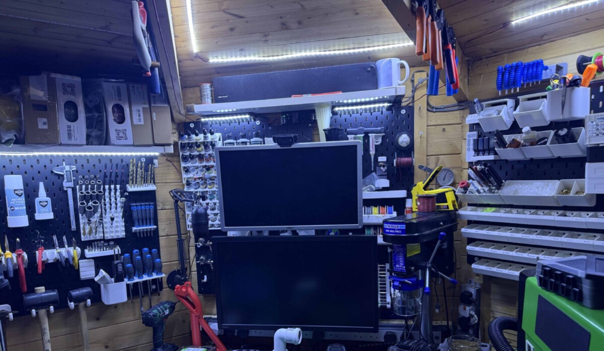
One of the first modifications i did to my machine used a 3d printer to make an mA meter housing. So i could stick on to the top of the laser cutter as don’t want to drill/cut my laser yet.
I finally decided to make something a little nicer. still not drilling my machine i know very unlike me lol.

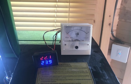
As the UK as the summer finally hit 32C warmth at last. but my water tank temperature has gone through the roof. so until i can afford a CW-5200 Chiller. Have gone back to 15L paint bucket and will be adding iced bottles every night so i can keep the temperature below the dreaded 25C, Unlike the last few days of 34C. So I have decided to design my self housing that is going to house a dual temperature gauge and my mA meter so i can monitor the temperature of the water coming in and going out of the laser tube.
Wiring up the wires:
Temperature Gauge water input/output temperature wiring:
I brought an inside-outside panel mount temperature gauge off amazon a few weeks back as like to keep an eye on water temperatures link for this here.

the downside is it comes with only 1M lead for each probe. i have ordered some 2M long ones from China but for this idea, i need them to be at least 3m long if not more. so i am going to make some extension leads up, I have ordered a box of JST-XH 2.54 connectors from amazon prime as wanted to knock this out of the park quickly, As from previous posts you might guess i am doing quite a few things on at the moment but love the pressure. link for parts here.
Time to make some extension leads. As a some one who like to make stuff, I have lots of wire kicking around going to start with the panel end of the extention lead, i am going to use red and black wire start off by crimping to JST-XH connectors to wires female crimps for the panel end. I then insert them into the 2 pin housing. you will need a JST crimp tool to do this.


now to probe end i am going to solder this and heat shrink it. So to do this plug the probe into the male connector then using my solder workmate. First of all, i tin the wires i then i run 3 pieces of heat shrink over the wires, 2 small to cover the pins after soldering and one larger one to go over the housing make it look nice and give it some strength. Then using my gripers I line the pin and wiring up before soldering them together.
Then using my heat gun i shrink down the 2 smaller bits over the freshly soldered joints. I then i slid the large bit over housing and using heat gun shrink it to the base of the housing is covered and connected to the wire.


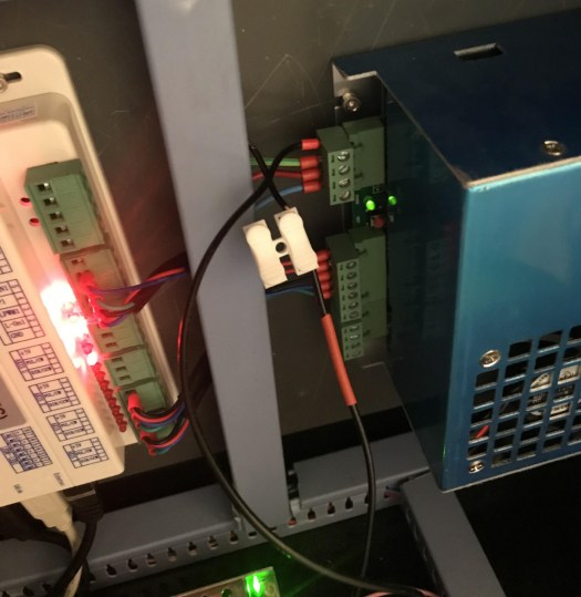
now to get power for the temperature gauge going to use 5v off laser power supply from 4 pin connector, not in use on the 50watt PSU so will use the Ground pin and 5v supply.


mA Meter Wring:
This is just a recap as did this a few months ago.

If you look at Laser PSU diagram above you will see L- on pin 1 this is were the mA meter will sit between. this wire comes from the low voltage end of the laser tube. (Laser PSU might be different from machine to machine) the principle will be the same though.
Now prep for the mA meter, As I have already did this so this is a copy from an earlier post.
The wiring I started by running 2 wires through the housing of the laser down to the electronics controller boards and power supplies of the laser. I will then crimp the 2 wires and attach them to the mA meter the + side i will attach some red heat shrink to represent the live side. on the mA meter, there is a minus sign telling me that the other pin is positive. as pictured below.


this will attach to the wire


All wiring done ready for the new housing
Enclosure Design:
As i have designed control panels in the past for my k40 laser going to use these elements as a template for mA and panel mount gauges i am going to use them in this design.
Now that i have proven my existing elements fit i am going create a box to house them both so where to start with this Inkscape has a plugin that will do this or there are many online tools that you can create a box. i have decided to go with http://jeromeleary.com/laser/ as i could add a sloped face to the front of the box as shown below. i then save dxf file and imported into lightburn.

I then added the elements for the gauge and dial to the box and added a rear cutout for the 2 sensors and power plug. mA gage as shown in the picture. below.

After doing initial design i decided to make some changes as once the housing will be glued together there would be no way to remove wiring so i added a brake out panel.

going to make a mockup in wood first and make sure it all fits before i go out and by some acrylic for the job,


Have redone file now the rear door emergency access doors are now better only 4 tabs to knock them out if any issues once glued. I have also changed dimensions on the mA meter as they were way off. I will test cut it again later and see if can get it to fit.

Now that I have proved it all fits together and works I am going order some acrylic to cut. I will be using 3mm acrylic in black so will look nice. I will also be using an infill process to make text stand out.
Acrylics arrived A3 sheet so now it is all fitting i can cut the final sheet

time to pull out my trusty airbrush and some white paint. time to do some infill before removing the protective layer.


Now time to assemble using some PETG adhesive to hold everything thing in place.


now to test all components fit.


right now all wired up without having to cut any holes now to hold it in place now for the 3M tape. time to test power on making sure temp gauge lights up. it does and mA is working fine.


all project files are available in Lightburn format and SVG, as i know not everyone, uses lightburn. link for lightburn software file and the SVG file
Thanks for reading next project think will be upgrading lighting in my 50w so i can get the lightburn camera working better thank it currently is for the camera. that will be once i find the roll off
