A happy New year to you all, Incoming parts have arrived so time to finish off this project last 6 upgrades firmware recompile and hopefully will be all done.
- Y-Axis Linear rail upgrade
- Neopixel install
Y-Axis Linear rail upgrade
You can get the kit I used here.
Yay The kit arrived when I was away so a bag of bolts and t-nuts aluminium end plates and base plates.
this is going to evolve some guesswork as with all china kits they never provide any instructions but basically will fit the 2 cross braces and add the rails to both and bolt them down will leave the supports lose so I can make sure all is plumb and attached the bed this is in theory fingers crossed.
Wow, they are tight going to loosen the frame ok now to centre them as best as I can. Now that I have the 2 cross members installed loosely to add the linear rails and 18 nuts and bolts on each rail to bolt them down lining them on the cross brace.
Now to mount the bed to the rails start with one side front bottom placing aluminium spacer and 30mm bot I fix in place I can see the left is off so nudge them to line up so I can put a bolt now to install the remaining 14 spacers and nuts. bed or carriage is attached I check it for lateral movement nice and smooth so I reattach the belts and repeat can that the top needs to come over. now I have it centred time to tighten everything up oh then looked at reference images of add noticed as i had 3 bits left that i couldn’t identify.
They are to make contact with the end stop. so add them now to install the rail end plates so another 8 screws and t-nuts. 4 aluminium covers later it’s done
Now waiting on spacers for the bed as I manage to lose once so should have them Friday also chatting with the vendor as my big tree tech package has gone missing in my absence. below is a montage of what happened through the build.


Neopixel install
Bit of 3d printing have found a led tape mount that I have modified to fit the gantry perfectly I am currently printing the bars in 2 parts will then print the end caps. 3 hrs later will just do a test fit tonight. ok, the first attempt failed so going to print into parts and have gone for a solid infill to reduce the movements see how it turns out. the bit that did print fitted though.

failed again argh going to look at slowing the print down to see if I can get it to complete

So added a raft fingers crossed. Update 50% done still holding.

made a mall 30mm section out failed parts and put 12v thought it to see if it lights and it did now to finish the cable.

right, this is going to be a bit of guesswork I will need to see how it pans out as I have changed my mind on how I am going to set it up but from what I can see I will need a 1000u competitor and 330k ohm resistor the competitor will go between ground and live and the resistor will go in line with data wire. I will make a 3 pin JST Xh connector so I can plug it into the mainboard this is the simple part. to install it I am going to stick the 18 LEDs to the top bar of the printer and stick it the v slot or I might stick it to some insert clips I have found that will allow me to stick it to it. still toying with this as I type this post. now the firmware is where I am going to start asking more questions as no one seems to be able to answer my questions. argh, have contacted support as they all seem to be for an earlier version of marlin firmware see what they come back with.
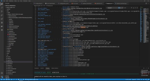
Figured I all out myself and was it a fucker so bugfix changes layout you will need to go ini folder in vs code fetures.ini and then change the following. go to adafruit comment on neopixle_led change to the following. NEOPIXEL_LED = https://github.com/CommandoreBombardiero/Adafruit_NeoPixel as shown below.

Now go configuration.h and search NEOPIXEL then change like below.

Then build it will fail with something about the delay so then go find Adafuit_neopixle@src- some numbers and letters you will need to change the location in the brackets to the location of your delay.h file in marlin/hal/shared/delay.h can see it for my dropbox location below.

build it again might fail but then if you build one more time success, wow my mind is numb now only taken the best part of 3 weeks on and off to get this to compile now to make and add connectors and hopefully, it works.

Next, up now I have it compiling is to make up a 3 pin plug so looking at pinout i know i will need a 3 pin JST connector and 3 crimps and JST crimping tool this is fiddly could also be done with Dupont connectors if you didn’t have JST ones kicking around.
Time to update the firmware wish me luck. sd card in hand. a bit nervous lol.
hmm, not working I am not sure if it’s the wire or something else going to check through my notes and see if it’s something like the wrong controller pin or it’s tested the wiring and got a continuity check on negative and positive.
checked over the firmware code and had assigned the driver pin as 4 instead of PA8 will flash the firmware again v4 I change the version number each time I make changes to the code.


Now to put every thing back together and add some cable managment an figure out a way to mount the unit to botom of the printer well untill i figure out my next mod more on that in part 6. will also need to re calibrate the first layer again hoping for the last time.
Once dialed in going to start running parts for the next modifcation going to take a few weeks to get bits in from china and ooznest also got to rework some bits as well. going to do the rework first before spending out on parts. as all these mods hav spireled out of control.
Next steps
When the bits turn up from china I need to enable filament runout sensor and power loss in the firmware but that’s a lot more strait forward.
Will make changes to config.ini for the screen when get the new bits as will allow the main board and Octoprint to communicate with filament runout sensor as that’s where its plugged in.
We’ll all short lived control box don’t fit under machine to going to make something better see part 6

