As i have had some issues with getting my lightburn camera to align and recognise all registration marks in calibration and alignment set up. I have decided i am going to add a better light source and see if this will improve the process.
first of all, i am going to identify current strip is running 12v or 24v or 240v so out with my trusty voltmeter. As i can see a 3 prong pin looks very similar to some i have seen on Amazon or aliexpress so once i know voltages i can look at my options. i am hoping its 12v as then will be as easy as buying a connector and digging out some led tape.
high voltage led strips so i have decided to go down the route of low voltage dimmable LED’s as cheap easy to fit.
Some fun with LEDs
As a maker, i had all the bits, apart from the led tape that i needed to order. So I found a cheap 5m kit off amazon prime as time is always an issue when ordering from China.
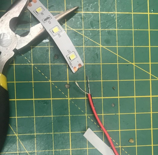
I have 50m of red and black, led wiring cable in my stock of parts. I started off by stripping the wiring off both wires and tinned them, I then took used my flux pen to clean up the terminals and added solder to both solder pads. I then soldered the wires to the pads.
All ready to tin and solder
I then used isopropyl alcohol to clean the area i was going to stick the tape to. I started bottom right worked the tape around the edge of the bed above the rim. Till it had gone around the bed.
all stuck down now to run the wiring
i added cable tabs to so i could keep some cable management i then threaded the wiring through the laser and out through a hole in the floor i then wired up a d 2.1 x 5.5 female connector to the end of the cable.
this is where i connected the dimmer switch and plugged the lighting into the mains
The end result looks good and hoping will cure my lightburn camera issues.
All wired up and working. yes, i will be cleaning my bed this week.
Next up:
I am going to see if i can now calibrate properly using the lightburn camera. if that works fine, I will design a slimline camera mount for the lightburn camera. As an issue with current cameras mount is the laser head hits is when running on the bottom of the printer.
One of the first modifications i did to my machine used a 3d printer to make an mA meter housing. So i could stick on to the top of the laser cutter as don’t want to drill/cut my laser yet.
I finally decided to make something a little nicer. still not drilling my machine i know very unlike me lol.
my existing housing.
As the UK as the summer finally hit 32C warmth at last. but my water tank temperature has gone through the roof. so until i can afford a CW-5200 Chiller. Have gone back to 15L paint bucket and will be adding iced bottles every night so i can keep the temperature below the dreaded 25C, Unlike the last few days of 34C. So I have decided to design my self housing that is going to house a dual temperature gauge and my mA meter so i can monitor the temperature of the water coming in and going out of the laser tube.
Wiring up the wires:
Temperature Gauge water input/output temperature wiring:
I brought an inside-outside panel mount temperature gauge off amazon a few weeks back as like to keep an eye on water temperatures link for this here.
new temperature gauge red is tank temperature blue will be returning water to tank temp.
the downside is it comes with only 1M lead for each probe. i have ordered some 2M long ones from China but for this idea, i need them to be at least 3m long if not more. so i am going to make some extension leads up, I have ordered a box of JST-XH 2.54 connectors from amazon prime as wanted to knock this out of the park quickly, As from previous posts you might guess i am doing quite a few things on at the moment but love the pressure. link for parts here.
Time to make some extension leads. As a some one who like to make stuff, I have lots of wire kicking around going to start with the panel end of the extention lead, i am going to use red and black wire start off by crimping to JST-XH connectors to wires female crimps for the panel end. I then insert them into the 2 pin housing. you will need a JST crimp tool to do this.
crimps done and first wire inserted in to housingFist crimp completed
now to probe end i am going to solder this and heat shrink it. So to do this plug the probe into the male connector then using my solder workmate. First of all, i tin the wires i then i run 3 pieces of heat shrink over the wires, 2 small to cover the pins after soldering and one larger one to go over the housing make it look nice and give it some strength. Then using my gripers I line the pin and wiring up before soldering them together.
Then using my heat gun i shrink down the 2 smaller bits over the freshly soldered joints. I then i slid the large bit over housing and using heat gun shrink it to the base of the housing is covered and connected to the wire.
ready to solder the first pin.Both soldered now to heat sink the connectorsNow for outer heat sink.Heat shrink installed ready to testTested and working one down now to repeatboth prob cables now done now just to run them.
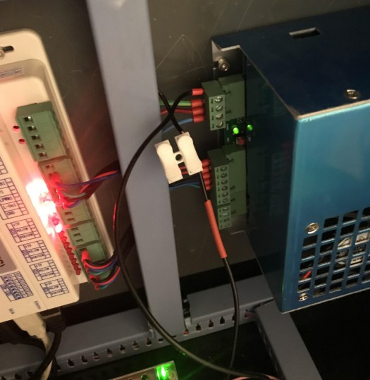
now to get power for the temperature gauge going to use 5v off laser power supply from 4 pin connector, not in use on the 50watt PSU so will use the Ground pin and 5v supply.
will use 5v and G to power my temp guage as will run on 5v minimal mA to power.power cable made for temperature gauge with pin crimps make it all match on the Laser PSU.power wired in for temperature gaugeright ready to go just need to cut my design
mA Meter Wring:
This is just a recap as did this a few months ago.
pinout for k40 style psu
If you look at Laser PSU diagram above you will see L- on pin 1 this is were the mA meter will sit between. this wire comes from the low voltage end of the laser tube. (Laser PSU might be different from machine to machine) the principle will be the same though.
Now prep for the mA meter, As I have already did this so this is a copy from an earlier post.
The wiring I started by running 2 wires through the housing of the laser down to the electronics controller boards and power supplies of the laser. I will then crimp the 2 wires and attach them to the mA meter the + side i will attach some red heat shrink to represent the live side. on the mA meter, there is a minus sign telling me that the other pin is positive. as pictured below.
positive connection cripmedadded some heat shrink to make it easy to identify after threading through the machine.both ends attached this meter only shows – so that will be going into the PSU ignore housing as new one will be installed later.
this will attach to the wire i will remove from the PSU going to use a terminal block for time being till i decide if i am going to cut a hole in my laser to permanently mount mA meter later on. the – side will go back to the PSU.
Wire to remove from laser psuremoved wire joined with temp connector will take the blue covers off tonight and add some proper bullet crimps to join the wires properly as happy it works.Now you would never know it been done bar the box on top of the machine.Working like a champ. in my soon to be old housing.
All wiring done ready for the new housing
EnclosureDesign:
As i have designed control panels in the past for my k40 laser going to use these elements as a template for mA and panel mount gauges i am going to use them in this design.
Now that i have proven my existing elements fit i am going create a box to house them both so where to start with this Inkscape has a plugin that will do this or there are many online tools that you can create a box. i have decided to go with http://jeromeleary.com/laser/ as i could add a sloped face to the front of the box as shown below. i then save dxf file and imported into lightburn.
my sloped fronted box design
I then added the elements for the gauge and dial to the box and added a rear cutout for the 2 sensors and power plug. mA gage as shown in the picture. below.
re arranged and added my elements and wiring outlet for wires.
After doing initial design i decided to make some changes as once the housing will be glued together there would be no way to remove wiring so i added a brake out panel.
V2 of my design the square on the back is brake away if any wires come loose
going to make a mockup in wood first and make sure it all fits before i go out and by some acrylic for the job,
Note to self make sure laser is in focus as had it set for something else doh still came out okWell it fits together temp cutout is fine but the mA meter is to small Wiring hatch is upside down so have now flipped it in the design will run again tonight.
Have redone file now the rear door emergency access doors are now better only 4 tabs to knock them out if any issues once glued. I have also changed dimensions on the mA meter as they were way off. I will test cut it again later and see if can get it to fit.
2nd attempt all fitting perfectly now to cut it acrylic
Now that I have proved it all fits together and works I am going order some acrylic to cut. I will be using 3mm acrylic in black so will look nice. I will also be using an infill process to make text stand out.
Acrylics arrived A3 sheet so now it is all fitting i can cut the final sheet
cutting time the smell of acrylic thankfully no complainants from the surrounding houses
time to pull out my trusty airbrush and some white paint. time to do some infill before removing the protective layer.
all sprayed up now to remove the protective layerstill got to polish and pick middles of some of the letters but you get the idea.
Now time to assemble using some PETG adhesive to hold everything thing in place.
glued and clamped on 2 sides5 of 6 sides glued. going to leave the top panel lose as the original plan did not work.
now to test all components fit.
fits perfectly on the machine now to bolt let the glue all dry and then wire it up.
right now all wired up without having to cut any holes now to hold it in place now for the 3M tape. time to test power on making sure temp gauge lights up. it does and mA is working fine.
Ready to stick new housingAll installed and workingRear wiring coming out of enclosure
Thanks for reading next project think will be upgrading lighting in my 50w so i can get the lightburn camera working better thank it currently is for the camera. that will be once i find the roll off
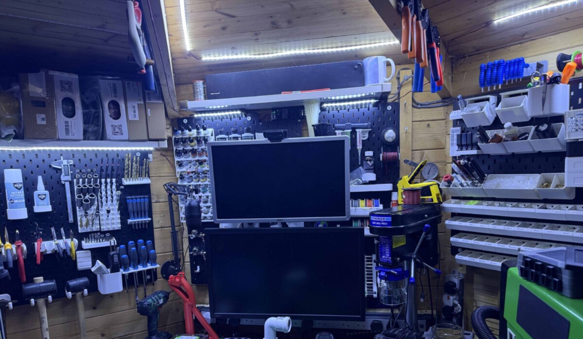
Right as one on my side projects is now done for another month. i can get back to doing enjoyable bits and get to finally clean up my workspace. get everything up and running and ready to work.
So last nights and tonight project is a freebie for my son’s nursery sports day for the toddler group some medals. with the heatwave starting to rush in not sure how much i can do over the next day or so but going to crack on and get the last 28 medals run tonight water temps allowing.
Designed a 2D trophy to give to the toddler and baby rooms of son’s nursery 28 per sheet.
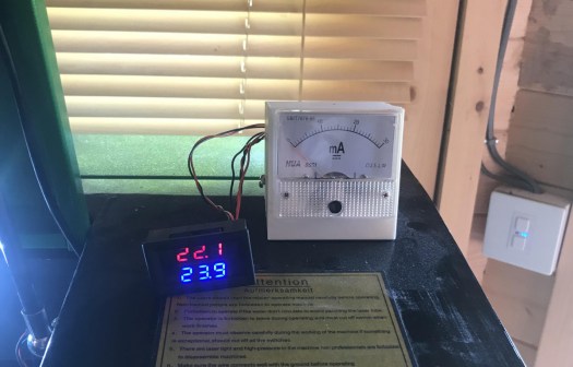
I taped up some 3mm plywood after i had sanded both sides with 400 grit sanding disc. placed it on my honeycomb bed top left. hit play and away the 50-watt laser went. i decided to crudely wire up my water temp gauge the water temp had started out at around 22c when i started to engrave
around 1hr later after the hole sheet had engraved the water temp was up a 29.9c
My temp wired water gauge in side ambient room temp gauge
This is my first attempt at mass production of a product and was an approx 2 hr of engraving and cutting of the medals with the worry of water temp raising 33.2c.
getting hot need a chiller.
this fun little project had given me some worries about water temperatures in the man cave.
I had found an original CW-5000 for £399 they had 11 in stock yesterday went to order today and they have sold out argh so going to bag some ice tonight and add to my distilled water.
Day 2 of opperation sports day medals and getting the mancave to opperatnal .
27 medals to go do love my 50watt laser so reliable fired up laser loaded lightburn put the new sheet of taped plywood and away we go.
final 4 engraving before the cut out pass.
All done and now to take all the tape off them 1 down 37 to go
taken off the tape off yash medal. going to also wipe with wihite viniger.
been a busy night on the tidying the cave now have a clean work bench getting a lot or the draws labeled up as need some organisation in the cave. starting to come together.
That’s me done for the night next operation is sorting the large form printer and my Prusa Mk3 both back online thinking about making some wall mounted spool holders as my enclosed one seem to be jamming up on me. Need to get the CR-10 up and working as well have to calibrate the machine.
Next project on the laser I have a stack of placemats to engrave for our holiday let but going to have to watch the weather and clean out the water tank and replace the dirty water. so will be doing that over the next week will cover the process and the tidying up of the cave at the same time.
Have in a three-meter Octagon is not the easiest of places to house as much equipment as i have. also as it has windows on 4 sides. So as i have Wednesday off with my son i had been into the local DIY store to grab some screws bits for another project i have been doing. This was a few weeks ago.
I picked up some 10 cm x 5 cm timber and sheet of plyboard to make a cover that went over the winds so i could mount my parts boxes. i had managed to hand saw down the sheet of ply and mounted over the window.
i then added screwed new parts draw i had picked up in the Aldi for £8.99 and my Budweiser sign. looked ok but was just a place to put parts.
Window cover board that i put to give me more storage space.
It worked well but was not quite what i wanted. I had just designed a template for holding Placemat and Coaster.
New jig for holding wooden placemats as have a dinner set to do for our house.
I then started to run a batch of placemats and coasters for our holiday rental property.
Engraved in Wooden placemat The Hollies Logo our rental property in wales.
As this was running I thought i would make a start reorganising things. so the Budweiser sign has been relegated to the attic. i move 2 of my other parts boxes around and dump bins allowing for a new shelf.
makes more sense having all my nuts and bolts fuses crimps and components in one place.
I then moved the dump bins racking so they were next to each other. I had an IKEA shelf we were going to use in the house. that i have installed for the moment above the racking.
Just got to sort through all dump bins and add to other storage.
i have started to print brackets for filament storage from the 3D printing nerds channel. So i will have shelving for the 2 boxes of filament i have freeing up more space hopefully. However, my Prusa decided to jam yesterday so will have to wait till come back from wales next week to fix.
Just before we it decided to jam up.
As i am working on the map and paid jobs i thought i would get everything up and running and remove bits i don’t need down to wales.
As then can do stuff when i am not in London so my K40 is going to be shipped off to wales along with the Prusa MK2s MMU and clear some space up for stock and parts.
this will be happening next month as will use a man and a van to transport bed and other bits as holiday rental property we have been developing is finally coming online should be available to rent in the next few months.
Next racking unit to sort is the CNC and vinyl cutter as its become a dumping ground and remove redundant bits ie water buckets for cooling as changed for a smaller type.
will be nice to actually get in the cave and be able just to work. Will be adding a download section to the web site so all my projects can be downloaded for free. maybe a project section to get some feedback and collaborate with some other bloggers.
Right got a 208 mile drive later after the day job hoping it will be a easy run.
Sorry for the delays in getting part 3 out i have had some teething issues with the lightburn but i have got a new way of tackling the issue.
The plan
going to break the cost up into a matrix grid of 8 squares and then cut the outline this will then be glued on to a bigger ply board that has been washed in blue to give sea effect.
after that, i will then cut each individual counties for wales. and then apply them to the large scale map.
Ok so that is the map sorted its now road names and places that i have to figure out how to apply. one mode of thinking is that just engrave them over the top of the counties another one is cut them out and glue them on top of the map. this will be my next thing to play with will post images of progress and testing as i so please bear with me.
now to find a some one to cut me a 1001 mm x 909 mm 6mm bit of plywood to act as backing board wilts i play with ideas on adding roads names and places of interest.
the joys of developing Technics for this fun project. next part to follow soon.
but an update is due i have been playing with the map a bit more have offset the roads to make the bolder on the map have also removed some names and features.
Managed to run the shading matrix now it’s not given me as many usable shades as i would have hoped but have a good 14 shades. think i need i have run the cutting matrix 2 times and will probably run it one more time to see if i can extract more shades in the future but for the time being i will run a total test. on 1 sheet of A3 wood but make it look as if 2 sheets. let’s begin part 2.
there was a error in my programming as 175mms line ran 2 times.
First run off the test matrix. can see the bottom scan line is way too burnt as predicted in last post.
tape removed form matrix
I removed the bottom line and made text bigger i also messed with speed of scan of text to make it clearer. Link here for SVG and here for LB files has been requested
modified file got at least 8 shades for counties
Still not happy with the overall test but i have identified the following shades for the map. i have named them so i can adjust accordingly going to run first a map just showing outline and counties.
65% Power 400 mm/s Anglesey
65% Power 350 mm/s Spare
65% Power 300 mm/s Flintshire
65% Power 275 mm/s Spare
65% Power 250 mm/s Carmarthenshire
65% Power 225 mm/s Ceredigion
65% Power 200 mm/s Denbigshire
65% Power 175 mm/s Powys
65% Power 150 mm/s Gwynedd
30% Power 300 mm/s South Wales
30% Power 275 mm/s Conwy
30% Power 250 mm/s Pembrokeshire
30% Power 225 mm/s Spare
30% Power 200 mm/s Wrexham
30% Power 175 mm/s Monmouth
Now to assign the shades to the map. as i have divided the map into multiple layers this will not be too hard to do just a little time-consuming.
shading assigned to the map
now to save it for a scaled test run to 300 x 500 bit of plywood I will probably have to run it slightly smaller as layout as constraints of scale as the final map will be run on 2 x 300 x 500 sheets.
Scaled for 1 sheet of plywood current size 350 mm wide and 380 mm in height
finished test run i will now add roads in different passes but before i do that i need to do a line test later on as i want the lines to be slightly different. but for the time being, going to test with the updated current setting. I also have issues with road names not showing right. as the images below the spaghetti junction so going to limit the map to show main roads in the area i really want to highlight in this map. also going to limit the name of places.
Roads added don’t look quite right.
Next Part: Coming soon
Adding Points of interest
Scaling and spiting the map over 2 sheets of 500 x 300 plywood
Making the map 3D by layering up the counties sea and mainland with roads and rivers i think but this is subject to change.
mounting it all in a frame ready to be taken to wales at the end of may.
Think I have been doing too many mods to machines instead of using them for some fun projects as so I have decided to show you the working of a bit of artwork I am putting together for our holiday home in Wales. this will be multiple layered pieces of art.
I will only cover the basics of the project as if you are used to using Illustrator and light burn you will know what I am talking about if you want more in-depth instructions please feel free to comment on the post. this will probably be over a few parts as going to be some trial an error as never done anything this scale.
part of the map i purchased
So after buying a layered map off maproom.net I then stripped assets from it using the layer selection in Adobe Illustrator. for example, I took counties outlines, place names, roads, road names, coastline rivers and lakes allowing me to take it across to lightburn giving me multiple layers this took a few hours and then to some vector path editing to pull off. I also noticed some issues with some of the vectors not being closed correctly so I had to address them as well.
Carmarthenshire outline selected before export.
I then named layers in ligtburn broke it down into the following layers this point I have not configured powers or speeds. as each county will be shaded differently. and some assets will be lines only were as other assets will be filled or outlined within the program. So cuts are just for reference at this moment in time I will post final speed and powers once I have run the test matrix i have made below
The map looks like currently, it’s oversized as will be cut in sections as will be using multiple sheets of ply to generate different layering to build up the A2 frame it’s going to be housed in. I will be cutting different layers then layering them ie. sea, land, then counties etc will be a bit of experiment.
Map in current form in lightburn
now that is all complete I will be looking at power and shading for different elements. so to start I have taken someone’s design and remixed to show greater ranges and speeds so I can see what different power/speeds achieve. Have named it shading matrix pallet. if you ask I will upload it for testing pleasure.
This is taped so I will not have to clean smoke off the wood think the lower speeds might be charcoal but will see later on tonight. upload my findings in part 2
Right got back London late last night this week is nearly done will be installing a new bed to the 50 watt laser tomorrow as just had to pay a minimal custom charge.
Should be delivered by parcel force tomorrow so fingers crossed. Tonight operation is fix the new heat bed and add the EZout to my CR-10 as manage to drop control box and rip wires out. before leaving to go to wales.
Still having issues with prob on and off might order a replacement as wanting my CR-10 back up and running.
Next project: end stops on my CNC machine so some drilling and tapping are required to mount end stops and some more mods for the control box as it’s sitting there taking up space if it’s not being used.
just about up to date to with getting steaming solution working will take it for a test drive soon then will probably start to do some small streams on a Wednesday.
Will add another post later hopefully with CR-10 news hoping for good news but got to recompile firmware as well. not happening as son is ill will resume tomorrow
Not setting any goals this week as its a busy weekday job and some RNR. I have got to go pick up some screws today so i can mount my baffle board to window for more tools and space for parts. then got to re assemble gun rack for my air soft weapons and hang some other bit. on new baffle board.
Then depending on time, it’s on to the Prusa Mk2s MMU as I am on a roll of fixing stuff the last couple of week. If I can/cannot fix it will be starting the mammoth print of bits for the Haribo edition as again its bits taking up space that can be used other projects.
Will also be my first time running PETG as a material. hopefully will be easy learning curve.
On other current projects:
Wist, I wait for the EZout probe to clear customs. I am going to run some more calibration prints probably tonight. as did try doing bigger print but had some issues with print sticking to the bed. probably just a tweek to the z hight offset.
over the weekend I have built octopi set up that I am currently getting up to speed via TeamViewer for plugins and adding stream feed to the studio might give it a quick test later see things are running right. once I have finalised that will clone the card and do it for the Prusa Mk3 using the pins off the controller board.
What next up in the cave:
Getting limit switches wired into the CNC machine. then I need to learn how to use it so will probably do this via stream so hopefully will get some help with getting all going.


You must be logged in to post a comment.