New project time: Dual temp gauge and mA meter housing.

One of the first modifications i did to my machine used a 3d printer to make an mA meter housing. So i could stick on to the top of the laser cutter as don’t want to drill/cut my laser yet.

I finally decided to make something a little nicer. still not drilling my machine i know very unlike me lol.

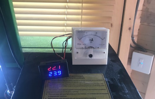
my existing housing.

As the UK as the summer finally hit 32C warmth at last. but my water tank temperature has gone through the roof. so until i can afford a CW-5200 Chiller. Have gone back to 15L paint bucket and will be adding iced bottles every night so i can keep the temperature below the dreaded 25C, Unlike the last few days of 34C. So I have decided to design my self housing that is going to house a dual temperature gauge and my mA meter so i can monitor the temperature of the water coming in and going out of the laser tube.

Wiring up the wires:

Temperature Gauge water input/output temperature wiring:

I brought an inside-outside panel mount temperature gauge off amazon a few weeks back as like to keep an eye on water temperatures link for this here.

new temperature gauge red is tank temperature blue will be returning water to tank temp.

the downside is it comes with only 1M lead for each probe. i have ordered some 2M long ones from China but for this idea, i need them to be at least 3m long if not more. so i am going to make some extension leads up, I have ordered a box of JST-XH 2.54 connectors from amazon prime as wanted to knock this out of the park quickly, As from previous posts you might guess i am doing quite a few things on at the moment but love the pressure. link for parts here.

Time to make some extension leads. As a some one who like to make stuff, I have lots of wire kicking around going to start with the panel end of the extention lead, i am going to use red and black wire start off by crimping to JST-XH connectors to wires female crimps for the panel end. I then insert them into the 2 pin housing. you will need a JST crimp tool to do this.

crimps done and first wire inserted in to housing
Fist crimp completed

now to probe end i am going to solder this and heat shrink it. So to do this plug the probe into the male connector then using my solder workmate. First of all, i tin the wires i then i run 3 pieces of heat shrink over the wires, 2 small to cover the pins after soldering and one larger one to go over the housing make it look nice and give it some strength. Then using my gripers I line the pin and wiring up before soldering them together.

Then using my heat gun i shrink down the 2 smaller bits over the freshly soldered joints. I then i slid the large bit over housing and using heat gun shrink it to the base of the housing is covered and connected to the wire.

ready to solder the first pin.
Both soldered now to heat sink the connectors
Now for outer heat sink.
Heat shrink installed ready to test
Tested and working one down now to repeat
both prob cables now done now just to run them.

now to get power for the temperature gauge going to use 5v off laser power supply from 4 pin connector, not in use on the 50watt PSU so will use the Ground pin and 5v supply.

will use 5v and G to power my temp guage as will run on 5v minimal mA to power.
power cable made for temperature gauge with pin crimps make it all match on the Laser PSU.
power wired in for temperature gauge
right ready to go just need to cut my design

mA Meter Wring:

This is just a recap as did this a few months ago.

pinout for k40 style psu

If you look at Laser PSU diagram above you will see L- on pin 1 this is were the mA meter will sit between. this wire comes from the low voltage end of the laser tube. (Laser PSU might be different from machine to machine) the principle will be the same though.

Now prep for the mA meter, As I have already did this so this is a copy from an earlier post.

The wiring I started by running 2 wires through the housing of the laser down to the electronics controller boards and power supplies of the laser. I will then crimp the 2 wires and attach them to the mA meter the + side i will attach some red heat shrink to represent the live side. on the mA meter, there is a minus sign telling me that the other pin is positive. as pictured below.

positive connection cripmed
added some heat shrink to make it easy to identify after threading through the machine.
both ends attached this meter only shows – so that will be going into the PSU ignore housing as new one will be installed later.

this will attach to the wire i will remove from the PSU going to use a terminal block for time being till i decide if i am going to cut a hole in my laser to permanently mount mA meter later on. the – side will go back to the PSU.

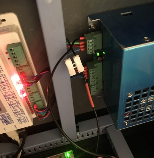
Wire to remove from laser psu
removed wire joined with temp connector will take the blue covers off tonight and add some proper bullet crimps to join the wires properly as happy it works.
Now you would never know it been done bar the box on top of the machine.
Working like a champ. in my soon to be old housing.

All wiring done ready for the new housing

Enclosure Design:

As i have designed control panels in the past for my k40 laser going to use these elements as a template for mA and panel mount gauges i am going to use them in this design.

Now that i have proven my existing elements fit i am going create a box to house them both so where to start with this Inkscape has a plugin that will do this or there are many online tools that you can create a box. i have decided to go with http://jeromeleary.com/laser/ as i could add a sloped face to the front of the box as shown below. i then save dxf file and imported into lightburn.

my sloped fronted box design

I then added the elements for the gauge and dial to the box and added a rear cutout for the 2 sensors and power plug. mA gage as shown in the picture. below.

re arranged and added my elements and wiring outlet for wires.

After doing initial design i decided to make some changes as once the housing will be glued together there would be no way to remove wiring so i added a brake out panel.

V2 of my design the square on the back is brake away if any wires come loose

going to make a mockup in wood first and make sure it all fits before i go out and by some acrylic for the job,

Note to self make sure laser is in focus as had it set for something else doh still came out ok
Well it fits together temp cutout is fine but the mA meter is to small
Wiring hatch is upside down so have now flipped it in the design will run again tonight.

Have redone file now the rear door emergency access doors are now better only 4 tabs to knock them out if any issues once glued. I have also changed dimensions on the mA meter as they were way off. I will test cut it again later and see if can get it to fit.

2nd attempt all fitting perfectly now to cut it acrylic

Now that I have proved it all fits together and works I am going order some acrylic to cut. I will be using 3mm acrylic in black so will look nice. I will also be using an infill process to make text stand out.

Acrylics arrived A3 sheet so now it is all fitting i can cut the final sheet

cutting time the smell of acrylic thankfully no complainants from the surrounding houses

time to pull out my trusty airbrush and some white paint. time to do some infill before removing the protective layer.

all sprayed up now to remove the protective layer
still got to polish and pick middles of some of the letters but you get the idea.

Now time to assemble using some PETG adhesive to hold everything thing in place.

glued and clamped on 2 sides
5 of 6 sides glued. going to leave the top panel lose as the original plan did not work.

now to test all components fit.

fits perfectly on the machine now to bolt let the glue all dry and then wire it up.

right now all wired up without having to cut any holes now to hold it in place now for the 3M tape. time to test power on making sure temp gauge lights up. it does and mA is working fine.

Ready to stick new housing
All installed and working
Rear wiring coming out of enclosure

all project files are available in Lightburn format and SVG, as i know not everyone, uses lightburn. link for lightburn software file and the SVG file

Thanks for reading next project think will be upgrading lighting in my 50w so i can get the lightburn camera working better thank it currently is for the camera. that will be once i find the roll off

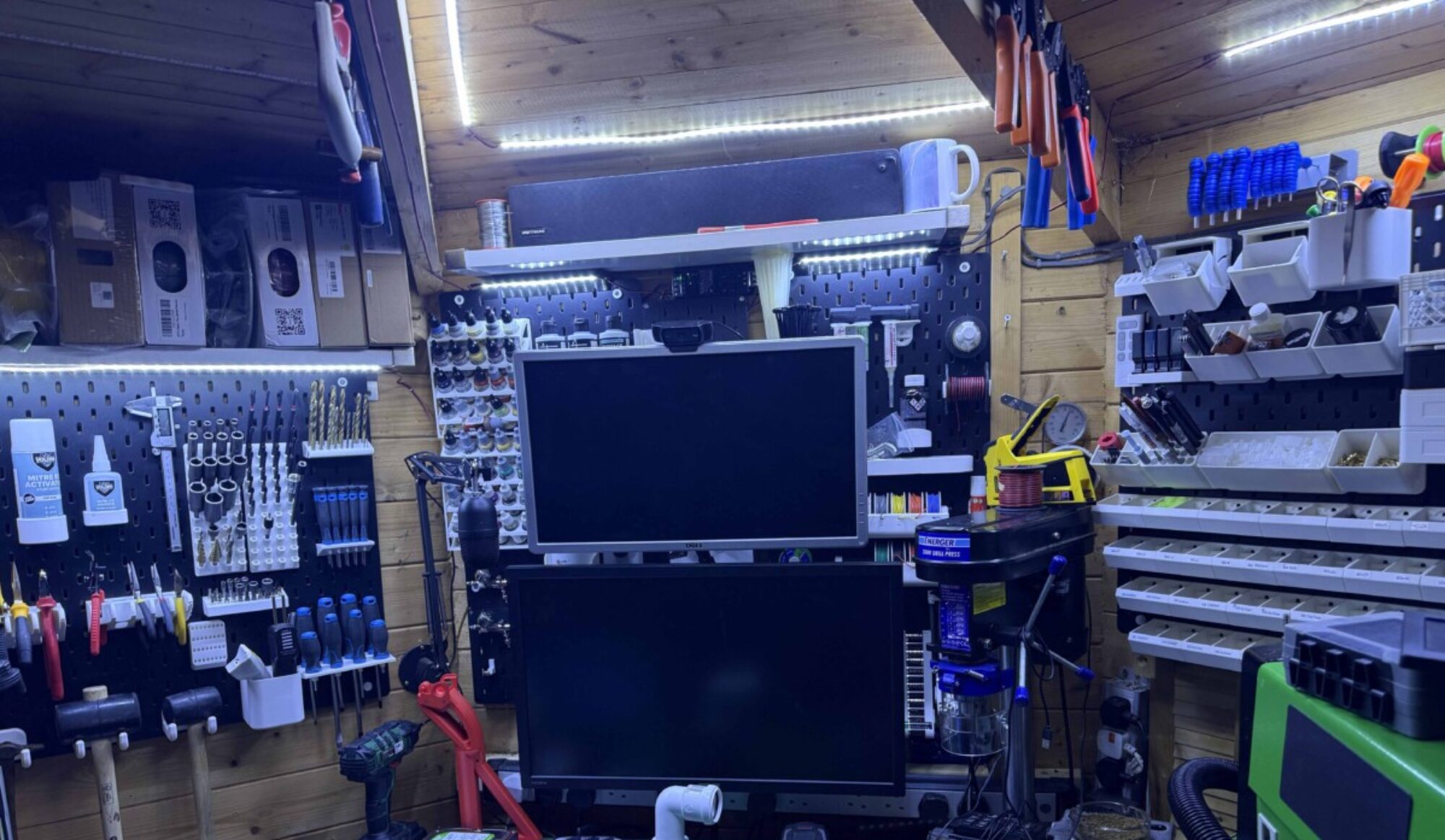
Spring cleaning in progress as fed up of not being able to use all my machines lack of space.

Have in a three-meter Octagon is not the easiest of places to house as much equipment as i have. also as it has windows on 4 sides. So as i have Wednesday off with my son i had been into the local DIY store to grab some screws bits for another project i have been doing. This was a few weeks ago.

I picked up some 10 cm x 5 cm timber and sheet of plyboard to make a cover that went over the winds so i could mount my parts boxes. i had managed to hand saw down the sheet of ply and mounted over the window.

i then added screwed new parts draw i had picked up in the Aldi for £8.99 and my Budweiser sign. looked ok but was just a place to put parts.

Window cover board that i put to give me more storage space.

It worked well but was not quite what i wanted. I had just designed a template for holding Placemat and Coaster.

New jig for holding wooden placemats as have a dinner set to do for our house.

I then started to run a batch of placemats and coasters for our holiday rental property.

Engraved in Wooden placemat The Hollies Logo our rental property in wales.

As this was running I thought i would make a start reorganising things. so the Budweiser sign has been relegated to the attic. i move 2 of my other parts boxes around and dump bins allowing for a new shelf.

makes more sense having all my nuts and bolts fuses crimps and components in one place.

I then moved the dump bins racking so they were next to each other. I had an IKEA shelf we were going to use in the house. that i have installed for the moment above the racking.

This image has an empty alt attribute; its file name is 2019-06-19-23.17.29.jpg
Just got to sort through all dump bins and add to other storage.

i have started to print brackets for filament storage from the 3D printing nerds channel. So i will have shelving for the 2 boxes of filament i have freeing up more space hopefully. However, my Prusa decided to jam yesterday so will have to wait till come back from wales next week to fix.

Just before we it decided to jam up.

As i am working on the map and paid jobs i thought i would get everything up and running and remove bits i don’t need down to wales.

As then can do stuff when i am not in London so my K40 is going to be shipped off to wales along with the Prusa MK2s MMU and clear some space up for stock and parts.

this will be happening next month as will use a man and a van to transport bed and other bits as holiday rental property we have been developing is finally coming online should be available to rent in the next few months.

Next racking unit to sort is the CNC and vinyl cutter as its become a dumping ground and remove redundant bits ie water buckets for cooling as changed for a smaller type.

will be nice to actually get in the cave and be able just to work. Will be adding a download section to the web site so all my projects can be downloaded for free. maybe a project section to get some feedback and collaborate with some other bloggers.

Right got a 208 mile drive later after the day job hoping it will be a easy run.

As last week went to pot

Not setting any goals this week as its a busy weekday job and some RNR. I have got to go pick up some screws today so i can mount my baffle board to window for more tools and space for parts. then got to re assemble gun rack for my air soft weapons and hang some other bit. on new baffle board.

Then depending on time, it’s on to the Prusa Mk2s MMU as I am on a roll of fixing stuff the last couple of week. If I can/cannot fix it will be starting the mammoth print of bits for the Haribo edition as again its bits taking up space that can be used other projects.

Will also be my first time running PETG as a material. hopefully will be easy learning curve.

On other current projects:

Wist, I wait for the EZout probe to clear customs. I am going to run some more calibration prints probably tonight. as did try doing bigger print but had some issues with print sticking to the bed. probably just a tweek to the z hight offset.

over the weekend I have built octopi set up that I am currently getting up to speed via TeamViewer for plugins and adding stream feed to the studio might give it a quick test later see things are running right. once I have finalised that will clone the card and do it for the Prusa Mk3 using the pins off the controller board.

What next up in the cave:

Getting limit switches wired into the CNC machine. then I need to learn how to use it so will probably do this via stream so hopefully will get some help with getting all going.

Life is good today

Yay works again.

CR-10 fixed don’t know how or why but all back in action god knows what cause of the problem. i ran a m48 probe test spat out some numbers. thought would give it one more go and did some more bed scraping but was for the greater good, i am now running a pre done profile with Simplify3D wish me luck. will post picture once it done

Before I fixed the CR-10 I have been running some squash ball feet for the printer, on my Prusa mk3. As they were all done and i managed to pick up some . . squash balls on the way home. AI decided to fit them see if dampeners will help with a ringing issue I have currently on te CR-10

Squash ball feet

nice and easy to fit using printers standard hard ware t-nuts and 4 dunlop double dots

3 feet fited one to go

been setting up my stream pad applications are all set just working what short cuts i am going to need. I have swapped over to streamlabs OBS. so I currently working on a setup just designing scenes for the system. I have written system layout ready so I can figure out what i need to need to buy camera wise and lighting. aiming to get some stuff up soon little nervous about the response I will get to my streaming.

Stream deck

and one finished cube next to 1 and 2 think its the best .

The first one is lasted version of print new profile. as the other 2 are relay wobbly.

now for the gramazon print if all is good or do I wait for EZOUT before I print. something that long as would be an pain in the arse if I run out of filament.

As i was on a roll with squash balls so brought 4 more and printed some more feet for my Mk3 will be fitting them tonight.

Feet for the Mk3

Will be fitting the feet tomorrow as today been with my boy so just been running bits in the background have set 90 % of my stream studio up and the stream deck is coming together.

done some diy cutting of boards and 2 x 4 for a frame im hanging in the cave for new tool rack will take some pictures when its up cheap way to add space

I have printed a frame mounted pi case for the CR-10 that i have modified through breakage so now open frame as the supports popped out the frame when they were removed.

will add some images tomorrow going to set up octopi tomorrow on the CR-10 as will make printing remotely easier also going to do the same for the prusa as have a spare pi kicking around.

K40 Upgrade Part 2 Control panel final cut and wiring & Installing new controller board and other mods.

This is going to be a mammoth Post. Have been buying in bits for the last few weeks to get this machine all upgraded to the speck that I wanted for a while.

was just going to be the controller board upgrade but me being me anyway enjoy the post feel free to comment.

I have designed a new control panel few posts ago. I will be adding it, In this post and taking care of a few mods at the same time.

As my time is limited has taken me a week or so to do all this with an hour here an hour there when the son was sleeping.

Parts list:

  • 1 x Custom Control Panel.
  • 1 x C-13  Custom Panel.
  • 3 x C-13 connectors female.
  • 3 x C-13 connectors male.
  • 3 x Power Led Buttons 240v rated. (Power on, Air assist and lighting)
  • 1 x mA meter from the original machine.
  • 1 x mA pot from the original machine.
  • 1 x 16mm push button latching switch LED 12v. (Laser On/Off Switch)
  • 1 x 16mm push button momentary switch LED 12v. (Laser Test Switch)
  • 4 x M3 x 25mm screws and M3 nuts.
  • 1 x 5v  3amp power supply.
  • 1 x 24v 10amp power supply.
  • 1 x  External Stepper driver 4 amp
  • Mains wiring Live Neutral and earth I have allowed 3m of each.
  • 1 x Cohesion3D Mini K40 Upgrade kit (including screen and lightburn software licence).
  • 1 x 3d printed bracket for side mounting laser power supply.
  • 8 x 3d printed spacer discs
  • 5 x 3d Printed bed adapters.
  • 1 x 3d Printed laser holder.
  • 1 x 12mm Laser diode with a cross adapter.
  • Updated laser mount plate.
  • Steel wire mesh for a new bed.
  • Bunch of m3 and m4 nuts and bolts

As I now have all parts in the mancave let’s kick this project off with printed parts

3D printed parts for a build:

I have printed sideways power supply mount,  I sliced and printed on my Prusa i3 Mk3 took  5hr 12mins to print.

I will need to move the installed power supply sideways so I can add additional power supplies for the extra 24v and 5v power supplies I will be installing on my machine.

Link on Thingiverse

Bed adapter for wire mesh bed.

Next up on the printer was some bed adapters I printed five as that’s how many screws held down the alloy plate to my machine. The Thingiverse file can be found here.

Bed spacer discs for bed.

I also printed some bed spacers so I can hold materials off the bed. This mod requires some m3 nuts and m3 hex bolts I had some kicking around I printed 8 for good measure might print some more. I measured 6mm off base for cutting 3mm material as I know that’s where my focal is set on cutting head. Link for spacer discs on Thingiverse. These took around 1hr to print.

Update printing a box load as see image laser cuts them like butter but for the sake of 1hr print for 8 I don’t mind just run 16 spares.

Laser Sight adapter.

I took used two designs and combined them to make my laser sight. So the ball holder and bracket links below.. and the ball for 12mm laser diode.. you will also need an m3 x 30mm and m3 nut t tighten ball in place once in position. You will need 2 x 25mm m3 bolts and 2 x m3 nuts to hold it to plate. This was around 30 mins for the ball and think 1:40 for bracket all done with no supports.

Link for bracket

Link for laser ball (only use ball)

Cutting laminated acrylic to size:

Next up to cut out the final control panel I will need to cut down the material I ordered from 903 ltd it’s a laminated acrylic so white on the outside black in the middle.

I have made cutting jig using two hand clamps and a spirit level. I will score the acrylic and then snap it. I have done this to allow it to fit in cutter note to self-order small bits next time.

worked well now have a piece of acrylic around A4 size perfect for the panel.

Final Prototyping of control panel:

I then did a final prototype in plywood as had adjusted the holes locations and sizes and make sure all fitted correctly as cannot afford to waste material.

Good job I did one more test as I will have to do one more test cut panel mounts are 5mm out and laser on-off switch text gets covered by the top panel so will move that across at the same time.

This is why you do have to prototype again and again till its right

So what started off as some simple changes I decided to change the font of digits around the power gauge and align all text make two holes bigger on the control display knob and brightness adjustment holes, I then enlarge the panel mount holes as well. To make sure all fits. Version 5.2f Final Version. I will upload the design to Thingiverse  Link Here

The Final cut in laminated acrylic 

After reading the material guide on cutting and engraving which is based on 30watt or 50watt helpful when I own a 40watt laser I did do some experiment using a small offcut as I had a big board cut down to make smaller pieces.

My findings were.


Cutting the Acrylic, I found that 15 mA and speed of 4 mm/s cut through the acrylic like butter I probably could have dropped the mA might do some more testing on this at some point

Engraving the Acrylic, I found that 10 mA and speed of 100 mm/s I did run at 70 there was a little more scorch marks on my test see above image.
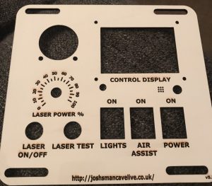
The Process I did cut pass first of all with the protective layer on I used double-sided tape to hold the acrylic in place on the bed on edges after the cut I removed the protective tape and cut parts. Then placed the cut piece back in cutout see images below. And run the engraving process. I also added furniture polish to the top layer this will help with cleaning after the process is completed.

I then uninstalled all switches and screen dial etc and moved them to the final resting before reinstalling control panel back in the machine.

I also cut a new back Panel for C13 Connectors that I had remixed to be labelled for the different outputs of the machine. this was test project so a lot more scorching but for the back of my machine, it’s perfect as won’t really be seen.

The Wiring:

Now the fun part wiring up the panel before I do the final cut in acrylic.

First off I re-install the mA meter, followed by mA pot,

Now to the additional two power switches and original switch. Using some crimps and mains wire I wired up a jumper cable that supplies power to all three switches

next came the two switches for the laser on and off and laser test wich.

These are very different to the originals. As five pins instead of 2 pins as you have NC, NO, C, +12 and  Ground.

  • NC = Normally Closed
  • NO = Normally Open
  • C = Common
  • +12 = + 12 volts in this case using 5v
  • Ground = ground side of swtich.

Now to wire these up, I to the two red wires for the on and off made a jumper cable so +12 and NC are wired to red cable one side and ground and common are wired to the other side of the switch. For the test button, I used the +12 and ground off the on/off switch to light the button when it’s on I then used the two original black wires on NO and C.

Adding the screen, this is held in by 4 x m3 x 25 mm screws I fed the screws through the panel and added 2 x m3 nuts behind it to act as spacers on each screw. I then fitted the panel and held it in place with further 4 x m3 nuts. 2 ribbon cables were then installed in ports exp1 and exp2 this I will connect to new controller board shortly.

Rotation of the Power supply I removed the four screws holding the existing power supply in place. I then attached the new bracket in place then using original fixing holes bolted power supply back to the bracket. I then aligned it and marked where I would need to drill then drilled 2 x 4.5 mm holes and mounted the bracket tightened down with bolts and butterfly nuts.

I then wired in 5v & 24v Power supply for lighting and laser sight. In a previous post, I had added LED tape to the inside of the cutting area and control panel area of the laser machine.  I soldered some more wiring on to get it to reach the newly installed power supply I also added the two wires for the laser sight they are both switched on using the light switch on the control panel.


Instaling the laser sight:

You will need an upgraded cutting head fixing plate. You will need to unscrew the three screws that hold the plate to the laser carriage. Remove cutting head from the plate and install into the new one. Then reinstall back on the laser carriage. After that placed two bolts through the bracket and aligned the laser with test mark, I had made on the material. I tightened bracket to stop movement I then unplugged laser and threaded wiring thought cable chain and plugged into 5v power supply job done.

Note: my eBay brought plate only let me fit 2 screws back in will have to modify the slot to fit the 3rd screw as out by 1 mm.

Installing C13 Panel for the rear of machine:

As requested here’s the link to my remixed c-13 panel get it here

I have decided to remove the 2 plug sockets from the rear of the machine as they are positioned badly the bottom one is very hard to plug in to. after looking through Thingiverse I found this simple C13 panel I remixed it slightly by adding some text for the aux equipment I wanted to run out of it. the air-assist is connected to a switch on the control panel whereas the water pump and fan vent run when the machine is switched on.

I started off by removing the 2 plugs I then got my tin snips and removed the metal connecting the plug holes I then fitted the plate and using an m3.5 drill bit I drilled the holes on either side of the c13 connector.

After that using terminal block connected the wires to the back of the c13 connectors.  I also added power for the additional 24v power supply for the stepper drivers and new controller board as the 2 sockets power on with power switch.

I then screwed the panel down using 6 x m3 screws and nuts.

Installing wire temp mesh bed:

I went to a local DIY shop and picked up some 50×50 cm fine diamond mesh. I used the original alloy bed to make measurements I then cut the sheet down to the same size using side cutters. I used 3d printed adapters on the top of each fixing point before installing the bed I then used original screws to reattach it to the bed.

as I know my optimal focus point is approximately 8mm off the bed I inserted spacer discs that I have printed to a hight of 8mm so my 3mm materials cut like a hot knife through butter.

Installing the Cohesion3D Mini K40 Upgrade kit:

Now that all upgrades have been installed to my printer and I am happy everything is working. I am going to go ahead with installing the Cohesion mini board and install the screen for time being I will be doing more upgrades for adjustable bed and rotary tool in the future but for now the board and the screen will do.

First of all, I removed the 3 nuts and bolts holding control board plate in place,

I then unplugged the 3 connections from the board 1 ribbon cable two Molex connectors I then undid the nuts holding M2nano board in place after this I installed new board redid up the nuts.

I also added holes and fixings for the 2 stepper drivers so I can add rotary attachment and z table at a later date. I will only wire up the for the rotary attachment atm as still unsure if I will use my light object z table.

I then added additional wiring for stepper driver and connected up to the  24v power supply and doe the control board.

I connected the screen connector and plugged in the first exp2 then esp1 as the guide explains. I inserted the micro sd card as well I then reconnected all cables.

I am having issues with the screen I have ordered a replacement. I am receiving support from C3D hopefully have it up and running soon.

need to tidy up the wiring at some point soon but for the moment I want to test.

time to test, I have already installed Lightburn on my pc.  to turn on my machine and see that it works. right all powers on and test button works.

It’s alive.


Next project for the k40:

Making a 3d printed Z hight adjustable bed off Thingiverse as the electric one I have brought is too small for my liking.

3d printing has begun about 20hrs to go.

Parts have been ordered so once they all come in I will be building this. will be adding a rotary attachment for doing round projects.

Rotary Attachment incoming from China via aliexpress.(currently in Germany should be with me by Wednesday according to FedEx) Now in part 1 of review is up now link here.

after that is done will be the end of my mods on the k40 for the time being.

Next Website Project CNC machine Enclosure:

This has been started Link Here


Been a productive week in the man cave.

Well, I have managed to do so bits in my spare five minutes here and there, Between looking after son and trying to get him into a routine. So we can have some time to do things we would like. so far it’s working but just a bit erratic.

I have built a PC to run the CNC controller software out of an old HP computer I had kicking in my office its nothing fancy will be running windows 7 and mach3 software provided with the machine. will cover this more when I do a review and set up a blog post soon. Already working on a waste board will be the first project I will run with the milling machine once all set up.

Have been running upgraded printed parts on my Prusa Mk3:

  • Printed K40 laser pointer printed for 12mm laser crosshair diode to be added.
  • Printed Dust extraction addon for my CNC machine.
  • Printed Camara mount for Mk3 so can record some live-action / time lapses for future videos once I have some time to do some. family first.

Ordered parts:

  • MDF for enclosure of my CNC machine and for a Waste board.
  • Laminated Acrylic for the control panel for K40 Laser. (going to have to cut it down as size is a little larger than I thought. )
  • 12mm Laser diode crosshair.
  • New extraction fan for K40 laser exhaust as other one is less than strong enough and when I start cutting and engraving acrylic I don’t want to be breathing the fumes.

Parts I need to order in the near future:

  • Perspex sheet for the front of the enclosure of CNC machine.
  • rare earth magnets to hold the front door in place.
  • A hinging mechanism for the front door of the enclosure.
  • dust cyclone extractor for a vacuum system for CNC machine
  • Water container for CNC machine cooler
  • Vacuum cleaner to run the system

Upcoming projects:

CNC Enclosure will be using my racking and some MDF to make an enclosure with a perspex door.

Wast board  for CNC machine this will allow me to clamp and grip parts for milling it will also be a damaged board so I can cut out pieces without damaging CNC bed,

K40 Cohesion3D Mini Upgrade, as you might have seen I have been designing a new control panel for this upgrade will be doing this around easter I would think as next period of time that I will have some free time.

CNC Chinese 3040 mill Build and Review

When building a workshop this one of them tool everyone should have in a dream scenario.  I was browsing facebook and sore one for a great price way cheaper than I had seen it anywhere else so was a no-brainer clicked and bought one.

The Drama:

I thought was too good to be true and in this case, it was.  Lucky I had paid via PayPal and managed to get a refund of the 299 NZD.  Do not buy from buildotory.com its a con and there is a whole group of people who did lose their money on Facebook.

The second time around I found a smaller version for a reasonable price from a Chinese seller in Germany.

3 days later 1 box turned up was a little worried as I had read it comes in 3 boxes, I contacted the seller who assured me the all 3 had been sent.

the next day 2 more boxes turned up. heavey boxes at that a whacking 53kg in total so walking them from my office to the car was a dumb idea that I did.

The Build:

As the wife was out with our newborn or coming back from wales I unpacked the machine in the house.

As usual with most things you order from China, there was no instructions bar a 350 meg file download link. this contained mach3 set up guide. a video that shows him setting up the machine not building it.

Don’t panic! it’s not that hard to set up 4 large hex bolts to attach the gantry to the bed of the machine then some small bolts hold the wiring chain to the base and 6 screws to hold the 2-bed skirts and cable chain runner to the frame.

After this you will have to connect all the motors with there connectors then it’s as simple as running the wires to the controller box. these wires are labelled X, Y, Z and A if you have the 4th axis like I do.

you will also need to connect 2 hoses for water cooled spindle if your version is the 800w the low rated versions are air cooled.

Software set up:

I downloaded the file that I had been emailed via seller it came with pdf on settings for mach3 in chinglish, it also came with Mach3 software in English and Chinese with patch files,

I followed the instructions and plugged in the USB cable to my laptop for time being.

once installed and all settings adjusted I tested it out. It alive have spun up the 800watt spindle and controlled it on all axis bar A as not installed as yet.

Things to note:

According to the seller, this will not work with 64bit versions of windows it does and windows 10 think this disclaimer was written about parallel port versions of the board which this isn’t.

The Near Future:

its now gathering dust in the man cave until I have some moments to build an enclosure for it. being as I will mainly be using for wood it’s going to need one as I don’t want to get dust every ware in my small man cave. Update I have ordered the boards to make the enclosure so should be up and be running soon.

I will be building it a pc to run mach3 as a stand-alone machine with vnc viewer on it. This is so I can remote in from master pc in the man cave will make easier for live stream setups in the future. Update Built PC just need to test it with mach3.

I have already taken the control box apart to have a look at the controller board.

From looking in the box  I can see there are spare pins for touch probe and end stops will be adding them soon.

see wiring diagram I found on the mach3 controller installed in my control box.

I have also ordered a probe to install and connectors to wire it up will install it soon.

I will review the machine soon as I have had some free time to set it all up

The first Project:

I have already designed a waste board for it as teaching myself CNC/CAM design as it simple to pick up as I already know how to use fusion 360 which has a cam package as part of the software. there are also other great bits of software out there.

Designing a new Control panel for my K40 Laser cutter. Part one design and layout.

As I have been modifying my machine as I go. I will be implementing the upgrade of the controller board this board will have an LCD screen output it’s going to need a new control panel.

so I have put this together using Inkscape and some parts of other peoples designs.

this is version 5.2c yes I have been working on this for a while as toying with different ideas and controllers was going to you push button style laser controller but decided against it. 5.2d as some of the holes were off and undersized. so have resized them.

I have cut this to start off with plywood as prototyping will be made of acrylic once I get it perfected will be making up the wiring loom shorty.

Just waiting on come crimps. will be adding 24 power supply and lighting 5v PSU to power internal lights when done. I will be also removing the 2 back plugs from the machine and replacing them with IEC C-13 connectors panel I have seen, this will make it easier to have external air assist pump and have the water pump and exhaust fan as well. going to use this design off Thingiverse.  IEC C-13 Connector Panel.

I will post more on the wiring of this as make up the wiring loom.

This is mains voltage so all being done right and not to be attempted if you don’t know what you’re doing.

Prusa i3 Mk3 Review

Finally, have had five minutes to put together a short review of the Mk3

After a fair few months, my machine arrived all boxed up. the PSU was a little dented soon pulled straight with needle nose pliers but apart from that arrived in good shape.

I decided to build this indoors as the bad weather and space is a factor when dealing with 100s of parts.

this is not my first Prusa kit. the last one took well over 8hrs to build and I did this over to days and then there were a few hrs tinkering to make it print well.

after seeing a few live builds from some of the youtube celebrities. I started it took a lot less time to build than the last one think I had the machine build in around 4hrs. had to do this over a fair few days though as little one had a cold and was in need of daddy time. I blame this for me messing up a few steps. will talk about that later.  the manual is epic and very well documented. I would, however, recommend using the online manual for bigger pictures and comments from users are always helpful.

after the build, I flashed the firmware to the latest version as there updating and fixing stuff all the time.

turned on the machine was greeted with would I like to run the wizard to configure my printer.  said yes it runs through fans bed and got to x then failed with the axis being too short. this had me puzzled for a few days. changed belt tension made sure every this was aligned.

turns out that I had missed a step in extruder assembly and inserted 2 bolts the wrong way around and was missing a few square nuts. hence why I blame macs (my son) as he cannot answer back lol.

once this was corrected ran the self-test again and it flew through without issues.  then calibrated z without an issue.

first layer calibration was a little awkward but think this was down to a firmware issue. as I have now updated firmware and my issues with prints not sticking seems to have gone away.

I printed an exhaust vent for my k40 laser it took 16hr to print. I did this as my first print as wanting to get as much done in a weekend so I can keep articles coming on the website.

I have now printed several of the test prints on the sd card see the images below and as always floorless.

I am yet to test out all the functions of the printer like power panic and was having issues with stepper motor crashes so turned it off as was messing up prints. I have not tested any of the functions since last firmware update. will add my findings to the review once I have tested them out.

my thoughts on the printer so far.

  • price is mid-priced but worth the money for the support and the features
  • quality is great every part fitted and there are spare parts just in case you drop that vital screw or nut.
  • easy to put together great instructions if you read them all Doh.
  • advanced features crash detection power failure and filament sensor I am yet to test but autoload works well just wish that they would implement the self-heat option when inserting filament.

I would recommend this to any hobbyist who is not experienced with 3d printers who want to learn and have a printer that will work out of the box without having to fix issues from poor manufacturing. this printer will produce high-quality parts in a lot of materials.


Hyper PI Bar Top Retro Arcade. Part 2 Wiring part assembly

Right, a little later than advertised in a prior post. didn’t get wrapped up till the early hours and still waiting on perspex so I can mount the monitor in the box.

started off wiring up all the buttons using the quick wiring loom

you have 4 wires to connect yellow and black are on the actual button on and off. the red and the black wires are for the led power they will only light if connected the right way around there are no markings.  So I would connect the USB board to a laptop and plug Molex into the connector board and loosely connect the red and the black if it doesn’t light first-way swap it over to get the button to light.

After wiring, all the buttons and joystick switches make sure all right if using a windows pc to check to open up joystick settings then can test all buttons and make sure the joystick is set up right as can reverse up, down, left and right.

After wiring all the buttons time to build the frame.

I brought a 100mm set of speakers that were not designed to be installed in this type of cabinet as universal I wanted to make some standoffs so I fired up fusion 360 designed the standoffs and then exported them to STL file which I then sliced and printed.

I then screwed these to the enclosure. I then started to slot the enclosure together as I am still missing the perspex I did not install. hoping that I can do that today.  the joysticks were a tight fit as the screws I used were a little longer than needed so I cut down the support bracket to get them to fit.

was fiddly but i manage to get it all together hoping for a delivery of perspex today so i can mount the monitor.

I decided as I am screwing all components to the baseboard I would print myself a raspberry pi 3 case to screw to the baseboard.

found a nice nettfab case on thingiverse.com and will install this tonight.

was getting very late so I decided to bolt down the joystick PCBs and call it a night.

will post more later today depending on the parts arriving today. will post some final shots of it fully working.