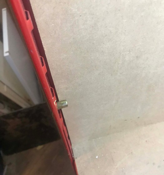
Taking a Broken CR-10 printer and throwing upgrades at it. Part 1

Will it improve its printing ability? or will it be an expensive mistake?

This project is going to kill or make my CR10 v1. The story so far :

2017 Received the machine from Aliexpress Creality store.

IT worked out the box did some big prints suffered from ringing kept vibrating off level suffered form glitches and so the story begins

brought the duel z modification less ringing started to get the hump with the board shaking the leaving screws lose. so decided to get the EZABL prob kit brought it got it all set up worked great had a major meltdown and destroyed itself with mass blob filament could not unclog it so I brought a complete extruder. took months to arrive. I disassembled the machine and put it in the attic.

meanwhile, I kept on using the Prusa mk2 that I keep on upgrading to the latest spec so forgot about the cr10.

Lockdown happened health workers needed PPE to save lives I joined a group of people making ppe. I started my print farm going 2 Prusa around the clock pumped out face masks ruffly printing 25 masks a day. but wanted to help more

brainwave I got that cr10 in the attic I can fix it as now 100 times more confident with repairing machines. So fixed the cr10 added silicon bed heater with SSR 1 good print out of my machine then for some reason the bed temp was reading very high in the 800c back in the attic went for another year have moved all business servers in the house so needed the space back so brought the cr 10 back down and put it in the workshop,

since then I have sworn at it a lot as keep tripping over and finally decided enough was enough swapped thermistor as thought that was the issue. it was but wasn’t, I finally figured out that it was the gunked connector in the control box that was that actual issue. fixed it after soldering a new connector into the plug on the box.

After a binge on Ali express and some more local parts, I’m going to modify the F#%k out of it and hopefully not go down in flames.

Let’s get this done.

I am going to lose the EZabl probe as has intermittent issues and the upgrade to a BL touch will mean that the EZout is no longer needed.

So thanks to the 3dprintingkid. I have been armed with a brand new ender pro 1.1.4 mainboard which I will be flashing with the BL Touch upgrade kit and latest Creality firmware. It’s already been flashed with a merlin 2.0x but going to go with the Crealitys version for the time being to see how it performs. if not will make my own compiled version.

So I will then have hopefully reliable levelling probe. next, I will be losing the Boden tube extruder for a direct dual drive upgrade off amazon with some belt tensioners being installed and proper z-axis motor mounts aluminium. I am going to upgrade the 8mm rods with some proper anti-backlash nuts.

Then it will give it a test whilst I wait for the next batch of upgrades to arrive from china within 10 days according to aliexpress.

So we are going to get a custom bed chassis, with an Upgraded Y-axis motor bracket.

then I will upgrade X-axis and Z-axis with a linear rails upgrade kit.

Finally, on to the frame, I will fit a stiffening kit and adjustable z rod holders with bearings.

Well, that’s the modification of the parts done. if they all work will be time to do some 3d printed upgrades.

Time to start.

Time to strip the machine down and swap out the old mainboard ready for the flash update. so first of all I have swapped over the cables and connectors from one board to another.

now to remove the old board from the machine. now to bolt the new board in the machine.

I will also loosen the y and x-axis belts and remove idlers ready for new ones. then will remove the extruder and extruder motor and PETG tubing. So I will be ready for the parts to arrive tomorrow.

A new day and a bit of a build ahead well once Amazon has delivered.

Got the first batch of updates,

Going to be a fun night

First up going to replace Y-axis tensioner with nice solid construction easy to fit.
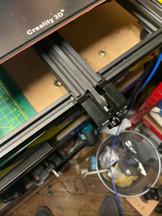
next up time to install the new extruder drirect drive kit.

Right next up to add the X-axis tensioner again solid construction the supplied screws are too long luckily had some M4 x 10mm screws kicking around nice snug fit.

Going to change the motor mounts as they are easier to fit 4 screws each and done much neater.

I installed a clone bltouch that didn’t work very well have been waiting on parts to continue the project. kept on crashing into the bed so ordered the official one from Creality

a week on and have most of the upgrades so now time to fit them all first up going to do the x-axis with linear rails. you can find the kit here have to take off my newly installed extruder and add the new rails.

That was very easy to do next up is the bracket on the extruder. it doesn’t fit what the F%&k I ordered the cr-10 v2 must have a different head on it. time to modify and make it work! if not will have to bite the bullet and order the correct one so out with my needle files and time to lengthen the hole. well 30 mins later now fits. but then the probe mounts don’t fit right. ok solved that put the bracket on first then nudged it over then the cover fits so looks like it will work I am now going to wire the official BL touch kit. won’t fit it yet as need to remove the x gantry to fit the z linear kit.

the one thing I will say about fitting all these parts is there are no instructions just wish that aliexpress manufactures would think about this as would make life easier for us end users.

Kit available here

only reffrence i have for assembling the rails.

time to strip down the z-axis and liberate it from the machine then to install the left and right z rail all fitted and now to rebuild x-axis with new brackets. the machine is starting to come together just need to fit the extruder.

had to rotate x motor to get it to fit with the bracket supplied. next up I fitted some side struts for rigidity lets see if they help. can find the struts kit here

all done ready for the extruder.

I just need to fit the BL touch and then do some cable management.

ok now to flash the firmware with Creality ISPprog.exe all done time test. lets do a auto home. argh, mods not allowing me to hit the end stop time for some mods some m3 nuts will act as spacers for the motor mount now works, as with any project some times just need to think out of the box.

time to flash the system

Right auto home x and y hitting wait a moment I have no z oh I see flashed it with standard merlin. Reflashed and all works had some binding issues with z that I have fixed by adjusting the threaded rod screws and my trust spirit level.

Now to offset z so we can start to test what the mods have done for this machine and will I be doing further mods let see quite nervous about the first print.

final bits to install z rod ends are now installed.

time to find a sheet of paper and see if my machine calibrates ok fingers crossed.

away we go auto home done over to Prepare menu then » Move Axis » Move Z now to lower the z till it grabs the paper and then make note of the amount and then go over to

In my case it’s -01.50 go up to the main menu then go Control » Motion » Z Offset enters —01.50 time to store the offset.

go back to the Control menu, then select Store Settings. The job is done now to test print

Failure of the bog-standard Creality firmware 1.60 has issues I think the printer is heating auto homing then going through the bed levelling part then it starts to extrude and rocks backwards and forward on the front of the bed. hmmm

F@@K it 8bit Creality board can go do one time to spend some money as I said going to throw upgrades at the printer till it works right.

Have ordered bigtreetech skr mini e3 v2 with TFT screen so will be compiling my own version of marlin for my 32bit board.

I think I will also swap to linear rails kit for Y-axis I might just sell on the custom bed as the kit comes with all the parts including the bed.

so I am going to end this here till I have the new mainboard and can make some progress.

more to follow.
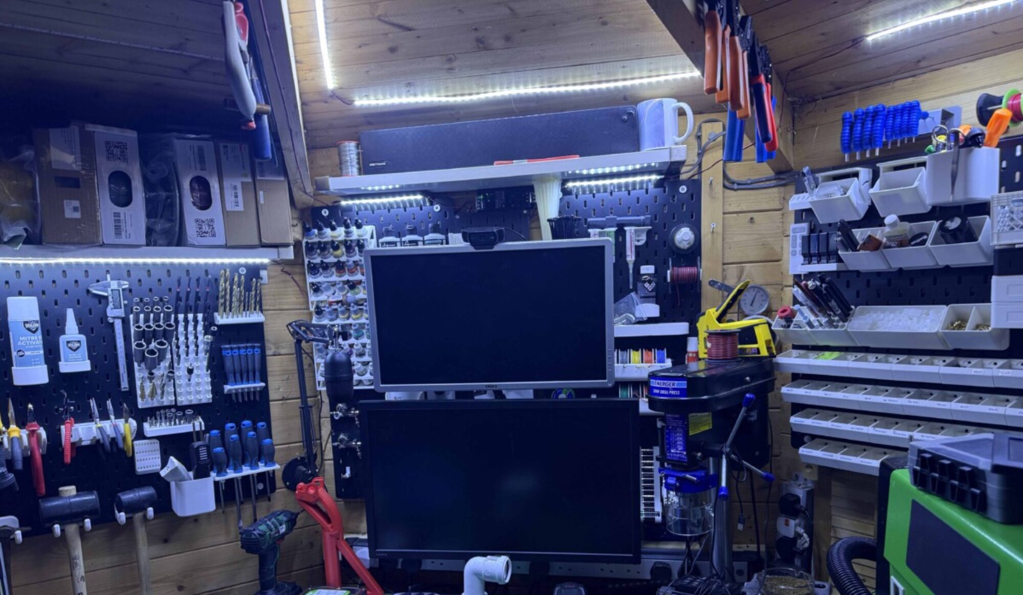
Why I love 3D printing

When you know how to make 3d models and prototypes 3d printer is one of your biggest assets in the small workshop. this whole project took 4hrs 30mins to complete from idea to finished working design and 4hrs of this was the print time.

Back story

As I am currently waiting for virgin media to fix an issue with my router before I can make the new website live as need to port forward from the VR machine. So to make sure i can just start to work on projects I am re-laying out the workshop. I have had tools sticking out of dump bins as I didn’t have a space to place them it’s got a little out of control. so back to the problem at hand and the point of this post.

The issue

Bocsh Wireless glue gun never found a handy spot for it. so last night after pulling out my callipers for some ruff measurements. I decided to make a handy wall mount.

The Mount Design

So fired up fusion made a 40mm circle and extruded it to 55mm then added a new sketch and made a new circle 35mm at on end of the cylinder I then cut into the cylinder 30mm I then added a 5mm hole through the middle and then using a bevel tool made a cone to exit.

I then flipped the design on its side and made a 55mm x 30mm rectangle I then moved it from the central axis to the outer edge of the design and extruded it by 5mm I then added 2 countersunk holes. by using a circle tool and the bevel tool. Now to export it to print.

Now to drag it into Prusa slicer and slice away made this design so won’t require any supports of rafts to print. printed with 25% infill. gcode ready for upload to octoprint. Away we go overnight parts was a 4hr print left it going as having rigged up relays for the lights and power of my printers so once completed it will shut off.

The next morning – The result

As you can see worked flawlessly apart from me being overzealous with my talk driver screwing it to the wall. but it’s perfect for my requirement.

My next job is to add a keyboard draw to my workbench using the track system but need to go grab some bolts and 50mm x 50mm wood from the local hardware shop.

CNC New Waste Board

New day new project after having a few failures due to double-sided carpet tape failing to hold bits down I have decided to modify my sacrificial board. saw someone do this on a youtube video so i have decided to make my own.

The Idea

Now as the board is bigger than max dims of the milling machine I am going to have to take some true measurements of limits of the machine. As the size of my sheet in the program.

I have these hammer in M5 t-nuts about 100 of them that brought a while back for this project. But then realized that the bed was smaller and my original plan would not work.

So I know the board size is 300 x 400 well according to the manufacture.  the wasteboard is actually sized as 380 x 550. Now to home the machine then figured out limits. In mach3 start off by homing all then zeroed X & Y. I then moved y and x to there limits and noted down the size in my case this was 227.6 x 387 so this is the material size. There is an extra 20 mm in x and y if I wanted as soft limits stop 10mm from each axis but happy with that as gives me room. Now on to the design side.

The design

This is double-sided job and my first attempt at one. So the first side is top side so going to my resurfacing tool to do a pass at .5mm as I know nothing has cut in that deep in the past. it will then do the edge bit

Then next up going to make a grid that is 25mm squares each square corner will have 6mm hole in it for bolt holes. To going to use v-bit to make grid followed by 6mm end mill to make holes the will stop 1.5 mm shy of the bottom of the board.

Side 1

Side 2 will have 17mm x 1,5mm deep circles over the holes to allow for the nut holders to be recessed into the wood.

Side 2

the rendered model looks a lot better.

side 1 rendered. i have lessened the grid depth
Side 2 renderd.

The process

I have already drilled 4 holes in the board to hold it in place i need to still get some shorter bolts and counter sink the nuts but that will be done after i have run the program

Side 1

This is going to be a 3 tool change process. we are going to start with 22 mm surfacing bit to a depth of 0.5mm to clean off any damage done to board it will then run around the edge of the board, the second pass will be drill function using 6 mm end mill. Finally will run v bit to make the grove grid. and outer border.

Side 2

One pass 6 mm end mill and the job is done. this pass will cut 1.5 mm depth 17 mm diameter circle so the trended inserts can be countersunk.

Running the program

Side 1

So first up the skim. in with my surfacing tool and time to zero it. do love the z probe script written by Charlie look at my review on the CNC machine for more details. right all set up to go have no idea on speeds and feeds on this. ok first and the second attempt failed miserably think i know why my rpm was far too slow so gave up for the night. new day new vigour lol did some light reading overnight and found my Spindle will go up to 24000 rpm i was running way slow for bit size so have adjusted tool to 18000 rpm from 1800 will try this again today.

Ok i am dumb i have miss calculated the size of material doh re-run the edges then hit the soft limits so did some recalculations and then rehashed my board completely.

Luckily being CNC no damage done so the board adjusted the gcode and off again i went with the board skimming. so process 1 ended up as 3 processes dont worry have made adjustments to the master files.

Some pictures of the resurfacing process. in process.

The re designed board:

Side 1 redesigned.
Side 2 re designed

Next up the grid. so out with the 30 mm surface tool. in with the v bit and time to zero the tool.

right holes tomorrow and then time to flip the board. hopefully will line up not sure if i should enlarge cut out just as the flip is the unknown hopefully will work out

Now to swap tools and put the end mill in and zero the tool. before running the 98 holes that need cutting. all ready for me to press start later. as the son had his nap got vacuum over the baseboard.

cleaned and ready to drill.

Disaster forgot to enable the spindle when on a destructive path gouging through grid i then reset but it had moved waste board and then ended up drilling through the bed in 2 places destroying 6mm endmill in process. managed to save it by flipping board so going to start again and not be so tired when playing with CNC machines.

Redone first 3 stages now for the flip going to finish off by drilling manual thought 2 halves as not to risk damage.

drilling done.
side 1 done.

Back on track and only another evening to waste on the board cnc humour.

continuing on with 6 mm end mill so no need to zero the tool final run of the cnc machine for this project. Well, i thought that was going to be the case but no i was wrong.

going to be glad to see the back of this project lol.

Right, this has gone a little wired on me as most of the circle are circle but some are not i think its to do with the soft limits stopping the bit from moving i think i am going to have t rethink side 2 of the board. Depth has not penetrated the holes so going to have to drill each one manually. oh and final fuck up they are not central to where i drill through the board.

So back to program and time to rethink design. the joys of doing things your self lol ill be worth it in the long run though lol. going to skim the board by 1.5 mm and then should be able to finish off machining of the board. I hope.

side 2 remixed for the 3rd time

will run that tomorrow as had enough tonight and it is 1 am again one day i will go to bed early. its a curse.

Another day first up out with an electric drill and six mill drill 98 holes to do drilled and now am going bolt the board down and run the skim and dam it, I have miscalculated the skim by 0.25 mm so time to modify the program. and run it again went well till dust shoe dropped had to kill the cut 20mm from the end of the run. Right enough is enough mach 3 g-code editing here we go figure out where it turns to run the last side edited the code to start there and away it went job done.

all skimmed ready for t nuts.
front re done

98 t-nuts to hammer in to the wast board and its done.

can see the damage it di in the first run and the skim i had to do and now hammer time.
all hammerd in now to flip it hope none fall out and mount it back on the bed.

The finished item only took week to run in the end all a good learning curve as most projects are already thought of my next project for the machine just need to get some aluminum and some M5 screws. also going to make some 3d printed ones as well.

all done at last.

Now to make some clamps over to fusion 360 to make my own as don’t want to spend out when i can design and make it my self metal and plastic

So that will be then next project should have 3d printed side done buy end of the week. that will be part one part 2 will be me teaching my self fusion 360 manufacturing.

keep reading.

Ok time for a new project well finishing one CNC enclosure and loose ends on the CNC machine.

Started stripping out the old hardware going to use a perspex window mounded to the unit with some flat head threaded rivets. Screw knobs 6 on the big window. then going to buy a A3 sheet if perspex and drill the 2 corners and cut a window out of the tool end with the same side panel but hinged on the top end. with to thumb knobs.

going to find some brackets to print to make the enclosure more scure.

will make sense when you see it.

Still not sure if i need a better dust collector going to get a mask as mdf is nasty stuff.

Going to re-run line vacuum line as it pulling the board also going to look at 65 mm dust shoe. to print.

But will work on that going to mount a camera on the outside of the enclosure looking in as the go pro went flat on me last night. then should be able to get good footage.

will start the documenting of it all tomorrow.

Starting to look at doing some fun stuff think i will get some hard woods to play with.

started looking at some dust shoes last night found one i realy liked the look of but its missing the brush part of the shoe. lots of people asking designer for it. no responce unlike most people who would just find another one. i desided to remix it with the brush attachment.

So pulled stl in to fusion 360 i then used it to reffrence shape and made the rest as i whent looks nice now to test it so first job of the day when i get to the man cave is to load the printer with some Petg and print this out.

this is the original design https://www.thingiverse.com/thing:2915093

orignal design

the part i designed is in grey on the image below.

bit in gray is what i designed as was missin from download
divits are for 6 x 2 magnets

I also made a inlay for brush strip to be inserted.

now to print it all

Just waiting on the wife to wake up from her sat morning lie in and will put some petg on the printer and start the print looks nice and compact so hoping will be more effective than the last shoe. as was a little bulky also means i can leave brush off and show you the cutting in action. as just held on with magnets. more later.

first part done now to test fit before i go any further.

First part printed will test fit it in a short while need to still dial in the other printer would be doing this with both running.

fits like a glove will now print the cavity part back in 4 hrs if i am still up and then will do the final part the bit i made and hopefully it all fits together. by tommorow will have a working dust shoe so far its nice and compact need to find some brush for it as mine is too big.

after diner will mark drill and make large observation window and make a mock-up for tool change window. then going to fire up my birthday present from wife a mini router and cut the window out that will probably be tomorrow if time allows. will then order some 4 mm A3 perspex and do i attempt to print my own hinges, hmm maybe i will to save some money.

also going to look for a enclosure camera mount or something that will suite my application.

So a bit of graft with some research more later

Ok! I sat down mistake I know just printing tonight will get this one off the bed then i will get the next one printing so by morning i should have a working prototype now to look for brush for the shoe.

second part done

Right 10 min cool down and will go remove it from the bed and start on the last part hopefully will all fit together.

away we go night all back tomorrow for more fun.

from design to production in less than a day do love 3d printing.

Morning all well afternoon had a lie in this morning was a late one. but parts are finished off. Will go down and see it fits before i apply the magnets as i have limited supply.

Just need to do a test fit. and find some brush. in fact that what i am going to do now.

It fits like a glove going to make a custom brush for it shortly might cut a broom down and hot glue gun the bristles in place.

will post remix shortly on Thingiverse and make public will post more images shortly once done hoping to do more on the enclosure later.

to make the above you will the following parts off Thingiverse.

https://www.thingiverse.com/thing:4460116

https://www.thingiverse.com/thing:2915093

Right Fitted the hardware and magnets have fitted it to spindle works well and is nice and compact has great suction too. just need to make the brush up next. not sure the best way to do this might buy a roll of PVC door blind material 2mm. and cut it down then make slits all around for brush part. limits are spot on got to love fusion 360 love my hobby licences free to makers and such a powerful tool i still need to do a course on it and learn its full potential.

Hardware and magnets inserted no need for glue limits spot on.
fits like a glove
zoomed out shot will do test tomorrow

Have started to drill holes for rivets i will then drill 2 fixing holes and mount perspex on to thumbscrews will drill these holes slightly bigger as gives me movement after i have drilled it then will drill a further 4 holes to racking so six screws in total. Drill batteries went flat waiting for a charge. before i mark and drill other holes.

2 holes drilled 4 to go then rivet time.

Think i will then move the suction hole to the top of enclosure might cut vacuum hose using 40 mm pipework to run a cleaner line to vacuum. going to do a test cut and see how it performs now with the different shoe.

Going to do that tomorrow as getting late again. will take a couple more shots later when i go take the battery off charge.

2 rivets in the hole just need to squish them need to change the head from 3 mm to 6 mm might actually do all the 3 mm holes first so i can then just concentrate on the 6 mm.

time to sleep back tommoorow.

Right been working on a day job in the man cave but have had time to drill and rivet all the side access holes.

I am going to get some cheap opaque 4 mm perspex from the local DIY store. and some insulation foam tape to stop dust coming out.

But that will be tomorrow as will be going out to the office. so will stop on my way back.

found a sacrificial broom to cut the bristles out of and glue into the shoe well that’s if i can get it to fit. The plan is to cut each bristle in 2 and put masking tape around the middle to holder them together till glued.

Will post images later. Going to run test cut tonight need to do some side projects for a friends gift but won’t cover that just in case he sees it.

Test run worked well wow the cave heats up and the vacuum is very noisy might have to see how to get a quieter vaccum.

Away way we go going with less dept and and more speed.

It turned out well going to need to do some minor sanding then to paint it.

all v bit cuts done just end mill pass to run

Just need to run the cut out pass but will that tomorrow happy with my progress going to get some different woods to play and some aluminum.

New 4 axis mpg.

Managed to install new MPG had some issue installing as it was not quite registering as in showed up on the PC but wouldn’t move. was about to send a shitty email to the ebay seller but. held off i consolted google and came up a blank i then remember last one dident like usb 3.0 plugs so I tried that. it then worked i will now to set up the macros as then can press button to do actions.

Did find a video on adding custom macros as want as the system uses it uses its own z prob script. the video showed how to get the mpg to work with 3rd party macros. to add z probe function and a few others. so i will start making a list of macros to add to the mpg. that might be a job of the day as the weather is not on my side today.

Will be going to the local hardware store later for some perspex and wood later. i managed to mark out the base board for its window cut out if the rain lets up later will cut it out when my son has is nap. as then can start putting things together. ready for perspex sheeting later.

little hard to see pencil marks but theirs a window there this is for quick access for changing tools.

right i will update more later if i can get it cut out today. the sun came out and the son finally slept window is now cut now to wake the boy.

Tool change window. now to seal it all up and make it dust proof it.

Tonight will screw it all together and make it as dust proof as possible. more later on this.

back from DIY store, i couldn’t get any perspex so got a sheet of 6 mm MDF will make it out of that for time being COVID-19 limited supply’s.

have marked it up ready to cut sheet down and add holes and rivets then will use foam backed tape to act as a gasket, will then use 3 x M6 screw knobs to hold sheet in place.

Cut the sheet down using my bosh multi tool cut though the MDF like butter. The MDF is temporary till i can get perspex. The joys of covid-19. i then drilled the fixing holes for the panel i then held up the MDF in position. I marked thorough the drill hole on the mdf. i then drilled the marked hole. I then fitted first flat rivet in the hole and fixed it in place with the rivet gun. then placed the MDF back ant attached it using the plastic M6 knob. I then marked up the renaming 2 holes. I then drilled them both and applied rivets to both holes.

New tool door quick access.

I then attached 6 mm insulation tape all around the window to stop dust escaping

lots of foam tape to help dust escaping.

I have also attached cabinet edge blocks through the enclosure to seal it up. need to get some more duct tape to seal to the racking.

its nice and snug

will take some pictures shortly but happy with it so far just need to play some more the system i think I might get a 1m hover extension pipe so it can be plugged in and out.

will measure that tomorrow and have a look at options.

have reprogrammed the mpg script so my z zeroing prob will now work on the mpg just need to figure out what custom macros i am going to install to it.

and it works liking this.

with to door off it gives great access to the front with 3 turn screws about 3 turns to release front and six to do the sides.

door open

I have a few bits to add to this project but they can be done as when i will update and post.

Complete resin coasters first attempt.

As i have lots of ideas for this will start off simple with some resin and ink with some star fx glitter and glow powder this might be cool it might be crap but intend to film it all the same.

I got some cheap silicone moulds off wish which i ordered over Christmas they finally landed so i have a mix of square and round coasters to play with.

Did some testing for a future project with some glow in the dark powder which worked well might do some moulding in a future project where i will show you how to make silicone moulds.

Now to do a Square coster so for this project i decided to some calculations on how much resin the coster will require as on my test i didn’t have enough resin to fill the 2 costers. so, in this case, i know the moulds 10cm x 10xm x 0.75cm which gives me a volume of 75 cubic centimetres 1 cubic centimetre = 1 millilitre so are going to need 75ml of resin per coaster.

As i am still a novice and will be using my starter pack of resin i brought from hobby craft. Pebeo Small Crystal Resin Kit will be buying more industrial sizes of resin in the near future as its quite fun to play with.

Safety first on with my nitrol gloves down with dead sexy pin Ikea silicon matt to stop mess on my workbench.

So this a 2:1 ratio so now for the maths 75 divided by 3 = 25 ml of hardener and 50 ml of resin out with the mixing jug for me. time to mix the resin do this in a gentle motion so as not to cause bubbles as i don’t have the money to get a vacuum vessel and pump at this moment. once mixed its time to add some colour as want this coster to be spacey i am going to add some Baja blue alcohol ink. I use the Jacquard Pinata Color inks as had them lying around from a prior project going to add drops till i get the right kind of darkness.

Next, the pour will fill the coaster halfway time to add some colour and sparkles and some glow powders going to use blue glow powder with some other colours this is totally free hand may look good may look rubbish but will hopefully be awesome.

got carried away with mix could more so do more. started off with the base blue but also pored one-pot with white ink and white glitter and white stars also added white glow in the dark powder the other with same just using silver glitter and stars and gold ink. will be putting the video together the next day or so just some shots to whet your appetites and yes it glows.

This was my second attempt.
this is my fav one of the 2 as did exactly what i was aiming for and did forget it glows.
great gas clouds perfect not to let it dry.

42 Drill and alan key Bits Storage shelf with added removal function

The problem

been buying quick release bits from wish and other suppliers just storing them in bags is not cutting it any more to time a made a storage tray for them all. was doing a tidy up in the cave last night came across more bits. put them in a draw. was lying in bed about to sleep when I had this design in my head last night waited till morning to put it into a design. the joys of dyslexia.

I had made a shelf for my retro pi NES box last night teaching my self new skills with tabs so i thought of what i had done and thought how to incorporate it with the design i was thinking of to make it a wall-mounted shelf.

So the principle for this is that all screwdriver hex bits are 1/4″ or for us, brits 6.35mm hex so on that principle i am going to do a test cut to make sure if i use the laser to cut that size it will fit if not will adjust its size.

first up lets design the tray going to be made up of 3 layers.

The first layer will be the baseboard and slider, Slider I hear you say what that for, all will be explained in the design. layer 2 and 3 will hold the bits.

Time to fire up my trusty Lightburn software to design and then cut it using a laser cutter.

Have made H counter leaver design for the wall if this does not hold the weight might go from tabs to another idea but cross that bridge when we come to it.

The first draft of the tool shelf with quick slide made the design up on the fly. for 4mm MDF

I will release the design once i have perfected it as with any project it might or might not be 100 per cent right the first time but let’s give it a go.

Time to test the hex size and then cut the full pattern, the joys of using light burn select the test part and then turn on cut selected graphics will only cut the one hexagon so i can make sure it fits.

Don’t forget to turn the option off after test cut.

Tested and yes i was right it was a little off and my thoughts of it being wrong were right so a little tweek. So now to test cut the design and make sure it all fits together before i glue it.

Wait I just thought of something to make it better!

Ok, i have decided to make 1 design change before the first cut to make the shelf more stable by adding second stabilization bar to stop any movement when taking the shelf in and out. the joys of having a dyslexic mind can figure out issues without even putting thigs down on paper.

Spot the 4 extra tabs in the design.
almost done.

So to assemble going to use 4 m3 screws and nuts to hold the 3 layers together will then mount to the wall using 2 X 4mm self tappers. going to glue using quick contact spray and glue.

Screws ready to put it together.
Screwfix special nice and cheap but great.
all glued right few issues but let mount it on the wall.

All glued let’s mount it and test it.

Not as tight as i want it. on the hex time to modify.

I am going to revamp the design slightly as a little too much play in the hexagons. and 2 back screws are binding so removed works fine so might just change base plate slightly to get it to work as well.

So back to the power of lightburn. Changed the dimensions by .300 in x and y to get a tighter fit. will test it tonight. I removed 2 back screws to stop it hitting the cross braces. I then took a few mm out of the back to stop it binding. will do cut of modified bits tonight and post findings later.

The fix changed the dimensions of the hex.

Will update this later once i have had time to cut modified bits. will then post the design.

did some more finessing of the design to make it much more usable have adjusted holes to make a tight fit and removed all bolts apart from m3 which are used for aligning the 2 hex panels during alignment and then glued boards in place.

the updated file works fine.
updated not bolts version just glued in place
all working fine.

Lightburn File download. please find a link to the file i have added information to the file that should be removed LINK

please enjoy and don’t sell my work.

I will be adding more videos

New projects got some fun idea coming up on the site already filmed the next video which i will post this evening. if time allows it as have been busy working on getting on of my rental property ready for new Tennent.

Have already filmed another video that one is more of an experiment to improve a project i saw over on a friends youtube channel.

So the next video is a how-to make quickly customizable keyrings for gifts using a laser cutter and lightburn software.

Followed by Resin pour using ink and glow in the dark powder if this works will lead on to a bigger project as thinking of doing some night lights for my boy using led fairy lights and some resin cast stars will be also making my own silicone mould to cast the stars.

Hoping to get my CNC machine working as well as want to do some cool stuff with that shortly.

got any ideas for a project and need some help drop me a line as always looking for ideas and would love to help some other bloggers or youtube channels.

More video content incoming with sound and multiple cameras if all works well.

Have had some technical difficulties with cameras and mic but think i have solved some of these issues hopefully by end of tonight i can film part two of the resin infill project so if all works will do this tomorrow.

very happy with the first attempt i have whizzed down the excess resin with my orbital sander and some 120grit sandpaper. Really need a sanding booth dust out brake think next time will do it outside.

some pitting from my bench not being level. now to make it shine.

Good News seems to all be working now just got to do some re-running of USB cables to get rid of the issues with running more than 2 HD cams on one USB port. Will test out the gaming headset for mic audio.

touch wood will all be good so i can film the final finishing of the coaster.

I am back in the cave time for some fun with UV resin.

Well 2 weeks off meant to feel rested but now more tired than ever the joys of life. Never mind time to play with my Christmas gifts as requested crafting supplies.

UV resin and some Epoxy Resin, as i travelled back alone i ventured down to the man cave last night for some testing.

so for my first test, i decided to try UV resin. on a silicon mould and infill on a bamboo coster that i had laser engraved. So i fired up lightburn imported a welsh dragon logo as the brother in law wants a set of costers. i set the parameters to 350mms and 70%-65% power with 6 passes. I will modify this in the future as i want it to engrave deeper in fewer passes. i then pored around 10ml of resin into a cup and added 6 drops of resin colour red to give a nice red resin using the stir stick i coated the engraving. then hardened using UV light. Now i had not removed the masking tape which was a mistake as when i peeled it took all the resin out of the engraving with the tape so started again with no tape didn’t now have enough to fill to level but get the overall effect was still stickie to the touch.

if it been the first attempt probably would have been perfect. just squeezed all i could out of the mix pot.

will sand it later and see what happens. then will repeat with Epoxy resin on the opposite side of the coster.

UV Resin test infill on bamboo after sanding. gives a nice infill even though i didn’t have enough resin.

The viscosity of the UV resin is quite thick and does not flow very well was going to use a syringe to apply resin but wouldn’t suck well. see how epoxy does. next up i half-filled a silicon mould with resin applied some dry flowers and then filled the mould with resin i then cured using UV light apparently need 30 mins only did a few mins so will need to try this again as very sticky after cure.

so time permitting will do some experimenting tonight as can see this being cool for some upcoming projects i want to do.

Plan B upscaling my idea octopi bigger screen build

Ok sorry for delays been a labour of love as have had issues the setup and getting wiring working right. but here we go. for time being i am going to simplify this post as serial links don’t seem to be working right will have a revisit to see what’s going on. might rework the wiring loom i made to see if that solves the issue. so running on USB

and even then last night had issues with that was trapped wiring, in the end, i have also ordered a 90degree USB cable to give some wire relief.

New USB cable seems to have fixed all issues with the printer sending kill cmd.

After having issues with my 3.5 TFT screen I now think this might be down to OctoPI-TFT not being a fully working build as i have rebuilt on my 3.5″ screen and 7″ to limited success. so i have decided that i have a 7″ touch screen and enclosure kicking around the man cave so i am going to install TouchUI on another pi yes got a few of kicking around will be directly linking via USB as serial links playing up. will also be installing power management with the plugin to turn my Original Prusa i3 Mk3s on and off independently to screen. also will be adding a led lighting ring around my web camera. this will be controlled by my octopi server using GPIO pins.

So what are you going to need to attempt this

7″ touch screen and enclosure.
Raspberry PI 3
  • 1 x Raspberry pi 3
  • 1 x Micro SD card 64gb overkill but smallest SD cardi have bar one in current set up.
  • 1 x Offical Raspberry Pi 7″ touch screen and enclosure.
  • 5v Arduino compatible relays. in my case 2 channel relay.
  • some duplex sockets and pins numbers to be confirmed.
  • crimping tool.
  • wire strippers.
  • wire, in this case, using a 6 core cable and a few single wires for lighting and any other additions as i build this project.
  • octoprint software available here.

Let’s get started First of all head over to Octoprints web site https://octoprint.org/ and download the 600+meg image start off by downloading the latest image.

you will need to unzip the image an image writer to burn it. I use etcher as it’s free and quick, select your image then select sd card as the target then hit start. a window pops up say yes to off it goes. will take around 15 mins to write and verify the sd card.

Select image from where you unzipped it.
Press start to write to the sd card say yes to the windows scurity alert.
off it goes time its verified will be 10 to 15 mins.

Now install the memory card into the pi and insert into the enclosure.

Then the power unit will reboot 2 times whilst it configures bits will be left with a screen showing the system ip and telling you to set up pi via the web browser.

Now time to install some bits in the background so we can tun this into touch screen printer controller.

You are now going to have to get an ssh client. i use Bitvise SSH Client as again freeware and very useful tool. so in my case i login to 192.168.0.50

you will then be asked for the default password of the pi which is raspberry. first things i tend to do is rename the host and change the default password. one to secure the pi and 2 to make it identifiable on the network.

type the following sudo raspi-config hit return this will then bring up the config menu. will get some legal bits about privacy and then be asked for the password again raspberry.

option 1 to change password for root
enter new password 2 times

You will then be greeted with the following screen

password changed you’re now secure.
select option 2 the option N1 Hostname then enter to rename.
then hit ok

Now go to finish you will be asked to reboot say yes. the system will reboot and you will need to open a new terminal window.

Bitwise will let you know when its back lives in my case can see it across the room. you will be asked for the new password when logged in click the new terminal window button will show your new hostname.

Now time to configure OctoPI with Touch UI Plug-in.

go to localhost.octopi or IP address that is displayed on your screen on boot up

First, of time, you go to the octopi web interface will be greeted with a wizard screen.

Image result for octopi setup wizard
  1. Start Screen
  2. Access control you will need to make up a username and password. then scroll down to enable login.
  3. Online Connectivity Check I enable this
  4. Plugin Blacklist I enable this.
  5. CuraEngine (<= 15.04. I skip this as all my files are pre-sliced.
  6. Default Printer Profile. Name your printer and profile also set up bed sizes in the tabs in the case of the Prusa mk3s it 250 x 210 x 210.

Now to do a quick plugin test run with my Prusa machine.

insert the basic screen.

Right now we have proof of concept. time to get on with making some connectors up and wiring to link to my Prusa using Rambo serial port. So as my other posts have found out the Prusa serial port does not have the amount of power to power a pi3 without the system having external power.

have clipped the red and black wire off as not using power from Prusa printer. going to make a 2×2 pin duplex female connector with blue and white wire and one with yellow and green. these will insert on to the following GPIO pins. 08 = white 10 = blue 15= green 16 = yellow this will give serial connection via Rambo board.

Image result for gpio pinout for raspberry pi 3
have included this GPIO pinout guide off element14.com website to aid with mods.

time to test again to make sure all connect correctly. success at last!!

Now to add power management and lights for the camera.

Now there are lots of ways this can be done using wifi plugs or relays in our case as want to make this a fun project going to use some 5v relays i was going to use some individual relays to make this project work but i have decided that i will use a 2 channel relay PCB that i will house in a housing as don’t want any wires sticking out.

Let’s make a start.

Taking note of the GPIO pins your going to use with this project in our case we will be using 2 x 5v relays so will use GPIO pins 04 for 5v+and 06 for ground.

IN pins will be any GPIO pins free so in this case, going to use pin 38 and 40 so GPIO20,21 as the triggers. for each relay, as will only use 2 to start might downgrade the relay at a later date.

Found this predesigned solution for 2 relays so will give it a go on Thingiverse

Link for the design can be found here.

i then jumped on PrusaSlicer and added the stl files. sliced them ready for printing.

not quite a perfect print but will do for the relay box.

Now have printed the relay holders will start on wiring side first one will be using 12vdc for light ring low voltage the other relay will be running mains voltage so do not attempt his if you are not comfortable with mains voltage. this is for UK spec wiring colour codes will change and if you’re in the states will not have an earth wire.

Let’s start with the dangerous element well not really that dangerous just be careful when messing with mains cables.

I tested it on my 4 channel relay to test the theory with GPIO pins switching without any power circuits connected to make sure it all works before adding mains voltage. my 2-way dual relay should be with me tomorrow. should take out shares in amazon as my prime account is much used.

!!!DO NOT HAVE LIVE WIRES EXPOSED WHEN PLUGGING INTO THE MAINS!!! makes sure all wiring is not exposed for anyone to touch i my set up i have mounted housing to back wall of the man cave keeps everything out general reach I also used terminated connectors with plastic sheathing to keep everything safe as a mains voltage shock is not fun. I have worked with high voltage for a few years and have been shocked several times the joys of playing with arcade machines and other industrial equipment. this is a disclaimer only attempt this if you feel confident with 240v wiring.

Relay 1

As i have a million and one kettle leads kicking around take a spare one and strip the outer sheath from it without cutting inner cores. i have a special wire cutter to do this and some wire cutters.

outer insulation stripped off i used coaxial cutter
wires cut then stripped .
added crimp pins i am redoing these in smaller pin size. as the yellows are too big squished them as a quick fix as testing.
240v end wired and strapped down.

You will be left with the 3 inner cores. cut the brown wire and strip around 5mm off each end. these wires i use pin crimpers as seals wire and makes it neat. the two wires will go into the high-end voltage of the relay so one will be on com or common pin and the other one will be put in normally closed or NC pin.

Relay 2

This will go via a mains powered 12v PSU i have wired this into the mains and taken some red and black-led wiring cable i have cut the red live wire and stripped 5mm each side and placed pin connectors on each end. placed into Com and NC connection terminals the same as above.

Low Voltage side of the relay to Raspberry Pi 3

on the other end of the relay, on the low voltage end, you have 3 pins IN, GND and VCC IN= GPIO pin GND = Ground and VCC= voltage input. GND and VCC will share voltage for the 4 relays. so will wire IN1 as the mains power switch and IN2 will control 12v lighting ring. leaving IN3,4 free for additional bits for the enclosure. so will make up 2 female pin duplex connectors one with 5v and ground. and the other 2 pin connectors will control lighting and power relay inputs.

low voltage wire will change with 4 pins instead of the current 6 pin

now the wiring is complete time to install some plugins.

ready for 12v PSU and mains voltage just going to test relays before install 2 relay PCB

all boxed up new 2 channel 5v relay ready to wall mount just going to make appropriate length cables.

tonight’s effort as most don’t realise this stuff takes time and has taken me a week to get all the bits together. tonight rewire operational and case installation. also testing plugins and doing an 8hr print. wish me luck.

Wiring swapped over to 2 channel relay and installed in housing.
all wired up ready fir 7hr test.

then armed with a hot glue gun i have glued my led ring to my cheap C922 Logitech webcam. some crimps and cable ties all attached i found an old hard drive power supply 12v that has 5×5 2.1mm power plug. to the parts to grab a female of the plug that i have so i can unplug it easily. The light is on now to install some plugins to control it.

Right ready to test just testing light as till i have a case for the relay i don’t want to risk mains voltage

i am currently testing out different plugins but work well.

Lights off

Lights switched off in my dark cave.

Light on all controlled by a plugin.

print for enclosure is done just need to pull it off the bed and fit the 2 channel relay to the box.

Ocoto-pi Plug-ins

going to run this through the enclosure plug-in so i will be able to power on and off the printer and USB camera light.

let’s get started

Touch UI plugin.

Go to the plugin management scroll down to get more and then search for touch UI after it’s installed you will be greeted with a request to reboot. do so

This screen will appear after reboot

when the server reboots you will be greeted with the new interface on the web log in don’t panic can switch this off look for the 3 bars on top of each other to the right of the screen. Click on it and sub-menu will be displayed click on TouchUI settings

click TouchUI Settings.
Click Toggle TouchUI to disable it on the web page.

The screen should go back to normal now.

Next step is done via remote terminal screen to install the front end for the 7″ screen.

Login to pi via ssh and do the following. Type the following to get the installer script.

git clone https://github.com/BillyBlaze/OctoPrint-TouchUI-autostart.git ~/TouchUI-autostart/

Now to install it.

sudo ~/TouchUI-autostart/helpers/install

Time for a reboot. sudo reboot now.

TouchUI should now display on your small screen were as a web login will be the same. you can customise it via the plugin under the web interface i made mine orange with black background.

Now to add functional add-ons to the system. will be installing a posting my findings in another post as this has been a week of tinkering but now happy with the output.

around 4 hrs till this finishes then will be adding add-ons.

nearly 4 hrs into wall mount spool holder. looks great.

Will be adding the following over the next few days and hard wiring the build.

Simple Emergency Stop

just what is says it i adds a E-stop to your menu bar as things do go wrong i usually sit watching the first layer or two print before going about my day and check in every so often.

Heater Timeout

this plugin saves your ass if you have forgotten to turn off printer hotend will allow# you to add a time out on hot end being idle.

OctoLapse

The daddy of time lapse captures with this powerfull plugin can make prints appear from nowhere. took a bit of reading to get this working right but worth the hard graft to get it working. mind you there is a pre-compiled version for the mk3 so might just try that.

Themeify

This is great custom themes discord being my favourite as i do not like white backgrounds.

PSU Control

this nifty little plugin will allow automatically shutdown of the printer after the print has finished also allows you to remotely turn on and off the printer.

OctoPrint-Enclosure

this will allow for all sorts of inputs and outputs i will be using it to switch on and off camera LEDs and maybe more in the future as might add temperature sensors in the future.

OctoPrint-PrinterAlerts

this plugin pauses the print if there any errors from Prusa printer sensors a must for a Prusa user.

FilamentManager

Filament Manager for OctoPrint yet to try this but seams promising for knowing how much is left on a spool will document this as i install. it.

This OctoPrint plugin helps to manage your filament spools.

  • Replacing filament volume with weight in sidebar
  • Software odometer to measure used filament
  • Warn if print exceeds remaining filament on spool
  • Assign temperature offset to spools
  • Automatically pause print if filament runs out
  • Import & export of spool inventory

CostEstimation

this allows me to price up my prints even if they are for my us as good to see how much i am spending.

OctoPrint-Complicated

As the wife has brought me a new iwatch for birthday i will be using this addon to see how my prints are doing via the iwatch.

OctoPrint-Dropbox-Timelapse

allows all captured time-lapse videos to be uploaded to my dropbox to stop any issues with my sd card filling up.