New Safety Panel for K40 Co2 Laser part 3

Been a couple of days I know since I posted last part. been fitting in bits between doing other stuff as having a nearly 14-month-old who is just about starting to walk keeping me busy as ever.  I also do not want to disable the laser for long periods of time. as got some gifts to get run up before I head off to Wales for holiday period.

I Started off by cutting wooden panel as will cut perspex one after the system is up and running as easy to swap over. also a learning curve as not cut perspex using the C3D mini board. so will need to runs some testing.

temporary panel for the control panel.
fitted all components bar one of the temperature gauges as was waiting on it to be delivered

after mock assembling the panel. I decided to put cutting disc to metal, so armed with Marker pen I marked holes and inner cutout box. I then centre punched holes before drilling.

ready for drilling and cutting.

I then drilled the 4 x 3.5mm holes and started the cutting process it took 3 discs to cut the cut out.

nearly cut out.

 I then realised As had made it to small as the standoffs for the main control panel and the bolts for the new one were not away enough so going to have to notch the other control panel to fit the nuts but trimmed down the bolts with Dremel so it fits.

now to mount back to the machine.

I fitted the other control panel to make sure it looks right in the machine. i started on the wiring last night by joining the positives and negatives for temperature gauges and running them both off 5v pin off the original power supply. as I have separate power supplies for controller board 24v  and 5v one for my machine lighting, my factory one is not overloaded. I will post a picture of them in action later on this evening as forgot to take camera down the man cave with me last night.  Tonight I will wire the LED’s and the flow switch in. and if i get time i will wire up the emergency stop button as well. will cover all this in a later post. 

Its alive! only issue is the 12v LED’s are too much power drain i might have to swap them out for 5v ones just he E-Stop to wire up now.

need to figure out what to do with LEDs

K40 Upgrade Part 2 Control panel final cut and wiring & Installing new controller board and other mods.

This is going to be a mammoth Post. Have been buying in bits for the last few weeks to get this machine all upgraded to the speck that I wanted for a while.

was just going to be the controller board upgrade but me being me anyway enjoy the post feel free to comment.

I have designed a new control panel few posts ago. I will be adding it, In this post and taking care of a few mods at the same time.

As my time is limited has taken me a week or so to do all this with an hour here an hour there when the son was sleeping.

Parts list:

  • 1 x Custom Control Panel.
  • 1 x C-13  Custom Panel.
  • 3 x C-13 connectors female.
  • 3 x C-13 connectors male.
  • 3 x Power Led Buttons 240v rated. (Power on, Air assist and lighting)
  • 1 x mA meter from the original machine.
  • 1 x mA pot from the original machine.
  • 1 x 16mm push button latching switch LED 12v. (Laser On/Off Switch)
  • 1 x 16mm push button momentary switch LED 12v. (Laser Test Switch)
  • 4 x M3 x 25mm screws and M3 nuts.
  • 1 x 5v  3amp power supply.
  • 1 x 24v 10amp power supply.
  • 1 x  External Stepper driver 4 amp
  • Mains wiring Live Neutral and earth I have allowed 3m of each.
  • 1 x Cohesion3D Mini K40 Upgrade kit (including screen and lightburn software licence).
  • 1 x 3d printed bracket for side mounting laser power supply.
  • 8 x 3d printed spacer discs
  • 5 x 3d Printed bed adapters.
  • 1 x 3d Printed laser holder.
  • 1 x 12mm Laser diode with a cross adapter.
  • Updated laser mount plate.
  • Steel wire mesh for a new bed.
  • Bunch of m3 and m4 nuts and bolts

As I now have all parts in the mancave let’s kick this project off with printed parts

3D printed parts for a build:

I have printed sideways power supply mount,  I sliced and printed on my Prusa i3 Mk3 took  5hr 12mins to print.

I will need to move the installed power supply sideways so I can add additional power supplies for the extra 24v and 5v power supplies I will be installing on my machine.

Link on Thingiverse

Bed adapter for wire mesh bed.

Next up on the printer was some bed adapters I printed five as that’s how many screws held down the alloy plate to my machine. The Thingiverse file can be found here.

Bed spacer discs for bed.

I also printed some bed spacers so I can hold materials off the bed. This mod requires some m3 nuts and m3 hex bolts I had some kicking around I printed 8 for good measure might print some more. I measured 6mm off base for cutting 3mm material as I know that’s where my focal is set on cutting head. Link for spacer discs on Thingiverse. These took around 1hr to print.

Update printing a box load as see image laser cuts them like butter but for the sake of 1hr print for 8 I don’t mind just run 16 spares.

Laser Sight adapter.

I took used two designs and combined them to make my laser sight. So the ball holder and bracket links below.. and the ball for 12mm laser diode.. you will also need an m3 x 30mm and m3 nut t tighten ball in place once in position. You will need 2 x 25mm m3 bolts and 2 x m3 nuts to hold it to plate. This was around 30 mins for the ball and think 1:40 for bracket all done with no supports.

Link for bracket

Link for laser ball (only use ball)

Cutting laminated acrylic to size:

Next up to cut out the final control panel I will need to cut down the material I ordered from 903 ltd it’s a laminated acrylic so white on the outside black in the middle.

I have made cutting jig using two hand clamps and a spirit level. I will score the acrylic and then snap it. I have done this to allow it to fit in cutter note to self-order small bits next time.

worked well now have a piece of acrylic around A4 size perfect for the panel.

Final Prototyping of control panel:

I then did a final prototype in plywood as had adjusted the holes locations and sizes and make sure all fitted correctly as cannot afford to waste material.

Good job I did one more test as I will have to do one more test cut panel mounts are 5mm out and laser on-off switch text gets covered by the top panel so will move that across at the same time.

This is why you do have to prototype again and again till its right

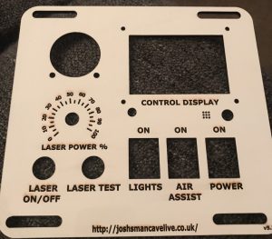
So what started off as some simple changes I decided to change the font of digits around the power gauge and align all text make two holes bigger on the control display knob and brightness adjustment holes, I then enlarge the panel mount holes as well. To make sure all fits. Version 5.2f Final Version. I will upload the design to Thingiverse  Link Here

The Final cut in laminated acrylic 

After reading the material guide on cutting and engraving which is based on 30watt or 50watt helpful when I own a 40watt laser I did do some experiment using a small offcut as I had a big board cut down to make smaller pieces.

My findings were.


Cutting the Acrylic, I found that 15 mA and speed of 4 mm/s cut through the acrylic like butter I probably could have dropped the mA might do some more testing on this at some point

Engraving the Acrylic, I found that 10 mA and speed of 100 mm/s I did run at 70 there was a little more scorch marks on my test see above image.

The Process I did cut pass first of all with the protective layer on I used double-sided tape to hold the acrylic in place on the bed on edges after the cut I removed the protective tape and cut parts. Then placed the cut piece back in cutout see images below. And run the engraving process. I also added furniture polish to the top layer this will help with cleaning after the process is completed.

I then uninstalled all switches and screen dial etc and moved them to the final resting before reinstalling control panel back in the machine.

I also cut a new back Panel for C13 Connectors that I had remixed to be labelled for the different outputs of the machine. this was test project so a lot more scorching but for the back of my machine, it’s perfect as won’t really be seen.

The Wiring:

Now the fun part wiring up the panel before I do the final cut in acrylic.

First off I re-install the mA meter, followed by mA pot,

Now to the additional two power switches and original switch. Using some crimps and mains wire I wired up a jumper cable that supplies power to all three switches

next came the two switches for the laser on and off and laser test wich.

These are very different to the originals. As five pins instead of 2 pins as you have NC, NO, C, +12 and  Ground.

  • NC = Normally Closed
  • NO = Normally Open
  • C = Common
  • +12 = + 12 volts in this case using 5v
  • Ground = ground side of swtich.

Now to wire these up, I to the two red wires for the on and off made a jumper cable so +12 and NC are wired to red cable one side and ground and common are wired to the other side of the switch. For the test button, I used the +12 and ground off the on/off switch to light the button when it’s on I then used the two original black wires on NO and C.

Adding the screen, this is held in by 4 x m3 x 25 mm screws I fed the screws through the panel and added 2 x m3 nuts behind it to act as spacers on each screw. I then fitted the panel and held it in place with further 4 x m3 nuts. 2 ribbon cables were then installed in ports exp1 and exp2 this I will connect to new controller board shortly.

Rotation of the Power supply I removed the four screws holding the existing power supply in place. I then attached the new bracket in place then using original fixing holes bolted power supply back to the bracket. I then aligned it and marked where I would need to drill then drilled 2 x 4.5 mm holes and mounted the bracket tightened down with bolts and butterfly nuts.

I then wired in 5v & 24v Power supply for lighting and laser sight. In a previous post, I had added LED tape to the inside of the cutting area and control panel area of the laser machine.  I soldered some more wiring on to get it to reach the newly installed power supply I also added the two wires for the laser sight they are both switched on using the light switch on the control panel.


Instaling the laser sight:

You will need an upgraded cutting head fixing plate. You will need to unscrew the three screws that hold the plate to the laser carriage. Remove cutting head from the plate and install into the new one. Then reinstall back on the laser carriage. After that placed two bolts through the bracket and aligned the laser with test mark, I had made on the material. I tightened bracket to stop movement I then unplugged laser and threaded wiring thought cable chain and plugged into 5v power supply job done.

Note: my eBay brought plate only let me fit 2 screws back in will have to modify the slot to fit the 3rd screw as out by 1 mm.

Installing C13 Panel for the rear of machine:

As requested here’s the link to my remixed c-13 panel get it here

I have decided to remove the 2 plug sockets from the rear of the machine as they are positioned badly the bottom one is very hard to plug in to. after looking through Thingiverse I found this simple C13 panel I remixed it slightly by adding some text for the aux equipment I wanted to run out of it. the air-assist is connected to a switch on the control panel whereas the water pump and fan vent run when the machine is switched on.

I started off by removing the 2 plugs I then got my tin snips and removed the metal connecting the plug holes I then fitted the plate and using an m3.5 drill bit I drilled the holes on either side of the c13 connector.

After that using terminal block connected the wires to the back of the c13 connectors.  I also added power for the additional 24v power supply for the stepper drivers and new controller board as the 2 sockets power on with power switch.

I then screwed the panel down using 6 x m3 screws and nuts.

Installing wire temp mesh bed:

I went to a local DIY shop and picked up some 50×50 cm fine diamond mesh. I used the original alloy bed to make measurements I then cut the sheet down to the same size using side cutters. I used 3d printed adapters on the top of each fixing point before installing the bed I then used original screws to reattach it to the bed.

as I know my optimal focus point is approximately 8mm off the bed I inserted spacer discs that I have printed to a hight of 8mm so my 3mm materials cut like a hot knife through butter.

Installing the Cohesion3D Mini K40 Upgrade kit:

Now that all upgrades have been installed to my printer and I am happy everything is working. I am going to go ahead with installing the Cohesion mini board and install the screen for time being I will be doing more upgrades for adjustable bed and rotary tool in the future but for now the board and the screen will do.

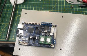
First of all, I removed the 3 nuts and bolts holding control board plate in place,

I then unplugged the 3 connections from the board 1 ribbon cable two Molex connectors I then undid the nuts holding M2nano board in place after this I installed new board redid up the nuts.

I also added holes and fixings for the 2 stepper drivers so I can add rotary attachment and z table at a later date. I will only wire up the for the rotary attachment atm as still unsure if I will use my light object z table.

I then added additional wiring for stepper driver and connected up to the  24v power supply and doe the control board.

I connected the screen connector and plugged in the first exp2 then esp1 as the guide explains. I inserted the micro sd card as well I then reconnected all cables.

I am having issues with the screen I have ordered a replacement. I am receiving support from C3D hopefully have it up and running soon.

need to tidy up the wiring at some point soon but for the moment I want to test.

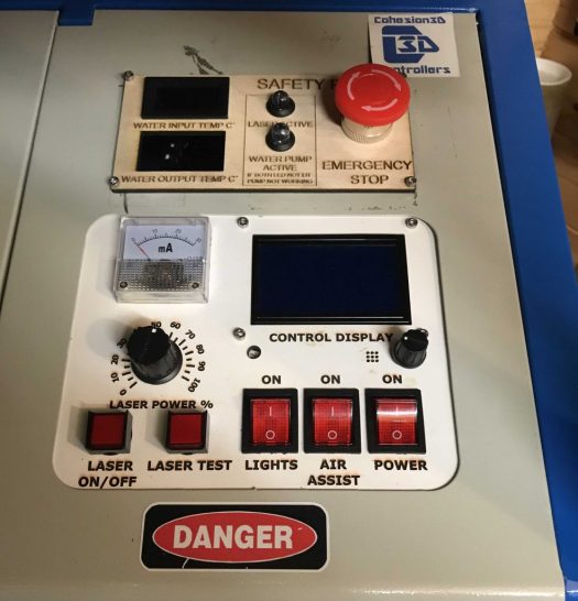
time to test, I have already installed Lightburn on my pc.  to turn on my machine and see that it works. right all powers on and test button works.

It’s alive.


Next project for the k40:

Making a 3d printed Z hight adjustable bed off Thingiverse as the electric one I have brought is too small for my liking.

3d printing has begun about 20hrs to go.

Parts have been ordered so once they all come in I will be building this. will be adding a rotary attachment for doing round projects.

Rotary Attachment incoming from China via aliexpress.(currently in Germany should be with me by Wednesday according to FedEx) Now in part 1 of review is up now link here.

after that is done will be the end of my mods on the k40 for the time being.

Next Website Project CNC machine Enclosure:

This has been started Link Here


Been a productive week in the man cave.

Well, I have managed to do so bits in my spare five minutes here and there, Between looking after son and trying to get him into a routine. So we can have some time to do things we would like. so far it’s working but just a bit erratic.

I have built a PC to run the CNC controller software out of an old HP computer I had kicking in my office its nothing fancy will be running windows 7 and mach3 software provided with the machine. will cover this more when I do a review and set up a blog post soon. Already working on a waste board will be the first project I will run with the milling machine once all set up.

Have been running upgraded printed parts on my Prusa Mk3:

  • Printed K40 laser pointer printed for 12mm laser crosshair diode to be added.
  • Printed Dust extraction addon for my CNC machine.
  • Printed Camara mount for Mk3 so can record some live-action / time lapses for future videos once I have some time to do some. family first.

Ordered parts:

  • MDF for enclosure of my CNC machine and for a Waste board.
  • Laminated Acrylic for the control panel for K40 Laser. (going to have to cut it down as size is a little larger than I thought. )
  • 12mm Laser diode crosshair.
  • New extraction fan for K40 laser exhaust as other one is less than strong enough and when I start cutting and engraving acrylic I don’t want to be breathing the fumes.

Parts I need to order in the near future:

  • Perspex sheet for the front of the enclosure of CNC machine.
  • rare earth magnets to hold the front door in place.
  • A hinging mechanism for the front door of the enclosure.
  • dust cyclone extractor for a vacuum system for CNC machine
  • Water container for CNC machine cooler
  • Vacuum cleaner to run the system

Upcoming projects:

CNC Enclosure will be using my racking and some MDF to make an enclosure with a perspex door.

Wast board  for CNC machine this will allow me to clamp and grip parts for milling it will also be a damaged board so I can cut out pieces without damaging CNC bed,

K40 Cohesion3D Mini Upgrade, as you might have seen I have been designing a new control panel for this upgrade will be doing this around easter I would think as next period of time that I will have some free time.

CNC Chinese 3040 mill Build and Review

When building a workshop this one of them tool everyone should have in a dream scenario.  I was browsing facebook and sore one for a great price way cheaper than I had seen it anywhere else so was a no-brainer clicked and bought one.

The Drama:

I thought was too good to be true and in this case, it was.  Lucky I had paid via PayPal and managed to get a refund of the 299 NZD.  Do not buy from buildotory.com its a con and there is a whole group of people who did lose their money on Facebook.

The second time around I found a smaller version for a reasonable price from a Chinese seller in Germany.

3 days later 1 box turned up was a little worried as I had read it comes in 3 boxes, I contacted the seller who assured me the all 3 had been sent.

the next day 2 more boxes turned up. heavey boxes at that a whacking 53kg in total so walking them from my office to the car was a dumb idea that I did.

The Build:

As the wife was out with our newborn or coming back from wales I unpacked the machine in the house.

As usual with most things you order from China, there was no instructions bar a 350 meg file download link. this contained mach3 set up guide. a video that shows him setting up the machine not building it.

Don’t panic! it’s not that hard to set up 4 large hex bolts to attach the gantry to the bed of the machine then some small bolts hold the wiring chain to the base and 6 screws to hold the 2-bed skirts and cable chain runner to the frame.

After this you will have to connect all the motors with there connectors then it’s as simple as running the wires to the controller box. these wires are labelled X, Y, Z and A if you have the 4th axis like I do.

you will also need to connect 2 hoses for water cooled spindle if your version is the 800w the low rated versions are air cooled.

Software set up:

I downloaded the file that I had been emailed via seller it came with pdf on settings for mach3 in chinglish, it also came with Mach3 software in English and Chinese with patch files,

I followed the instructions and plugged in the USB cable to my laptop for time being.

once installed and all settings adjusted I tested it out. It alive have spun up the 800watt spindle and controlled it on all axis bar A as not installed as yet.

Things to note:

According to the seller, this will not work with 64bit versions of windows it does and windows 10 think this disclaimer was written about parallel port versions of the board which this isn’t.

The Near Future:

its now gathering dust in the man cave until I have some moments to build an enclosure for it. being as I will mainly be using for wood it’s going to need one as I don’t want to get dust every ware in my small man cave. Update I have ordered the boards to make the enclosure so should be up and be running soon.

I will be building it a pc to run mach3 as a stand-alone machine with vnc viewer on it. This is so I can remote in from master pc in the man cave will make easier for live stream setups in the future. Update Built PC just need to test it with mach3.

I have already taken the control box apart to have a look at the controller board.

From looking in the box  I can see there are spare pins for touch probe and end stops will be adding them soon.

see wiring diagram I found on the mach3 controller installed in my control box.

I have also ordered a probe to install and connectors to wire it up will install it soon.

I will review the machine soon as I have had some free time to set it all up

The first Project:

I have already designed a waste board for it as teaching myself CNC/CAM design as it simple to pick up as I already know how to use fusion 360 which has a cam package as part of the software. there are also other great bits of software out there.

Designing a new Control panel for my K40 Laser cutter. Part one design and layout.

As I have been modifying my machine as I go. I will be implementing the upgrade of the controller board this board will have an LCD screen output it’s going to need a new control panel.

so I have put this together using Inkscape and some parts of other peoples designs.

this is version 5.2c yes I have been working on this for a while as toying with different ideas and controllers was going to you push button style laser controller but decided against it. 5.2d as some of the holes were off and undersized. so have resized them.

I have cut this to start off with plywood as prototyping will be made of acrylic once I get it perfected will be making up the wiring loom shorty.

Just waiting on come crimps. will be adding 24 power supply and lighting 5v PSU to power internal lights when done. I will be also removing the 2 back plugs from the machine and replacing them with IEC C-13 connectors panel I have seen, this will make it easier to have external air assist pump and have the water pump and exhaust fan as well. going to use this design off Thingiverse.  IEC C-13 Connector Panel.

I will post more on the wiring of this as make up the wiring loom.

This is mains voltage so all being done right and not to be attempted if you don’t know what you’re doing.

New Exhaust ducting and fan For K40 Laser cutter

As i had a week end  moving stuff around in the man cave as family where away for the week end i have had some time to re jig things in the cave. It is far from perfect but will do for the short term.

Finally had time to build my Prusa i3 Mk3 as my other 2 printers are in need or repair.

I thought for the first print that i would make a new extractor for fumes as much as i love the smell of burning wood. it can smell quite pungent.  when i start cutting other materials like acrylic it will probably not good to inhale.

the reason for this is the one provided with the K40 is a bad  very cheaply manufactured device that i does not work very well as it dose not sit properly and leaks. also the fan is very badly made.

After looking on thingiverse i found a few designs that i like the look of but settled on this one  as would just fit on the MK3 print bed.  with the a glue stick i got it to print in 16 hrs using 0.2 layer height.

It turned out very nice. i brought some 100 mm tumble dryer vent tubing that might have to change as noticed yesterday that it already got holes in form dragging it around the man cave. will be cutting 100 mm hole in the wall to add a vent in the future or cracking a window to hang it out.

i then attached it to a inline fan and added more tubing the other end i am not convinced the fan i brought is powerful enough but will update this if i have to update the fan.

will be reviewing the Prusa i3 Mk3 soon after i have done some more prints.


Light Object Cutting head and air assist upgrade of new mirrors and adding led lights.

Be warned if you’re in the UK import tax is killer on USA imports atm. For mirrors and lens cutting head and the motorized bed had to pay a further £80 in tax.

You will need a cheap pump for this paid £15 for one-off amazon.

Removal of the old cutting head in my case just twisted and it came apart. Removed old cutting head.

Added new mirror and lens to light object cutting head and reinstalled.

Change other 2 mirrors as easy to remove and change you just need to unscrew the cover and replace with the new mirror.

Then realigned the mirrors for the new set up.

Took 2 weeks in the end to align lens and mirrors this was my own fault as I had used an angle girder to cut down my exhaust it had vibrated all mirrors out of alignment loosen mirror mounts.  I managed to bring it in from the man cave as son and wife were having some time with family in Wales.  The joys of dad life and before you ask I wouldn’t change it for the world.

Next up I  installed the cable chain I brought off Amazon,  to hold this on I used 2 cable ties through the laser carriage and shortened the other end of the chain I then stuck the other end down with 3M double sided foam tape.  I then run the silicon tube for air assist. in to control box part f the printer, there is a spare hole at the back of the enclosure I ran the silicon tubing through there.

i then have attached pump which is plugged into the mains i will be making this controllable of my custom control panel once i get some time to build it so probably over the next few weeks.

as i know the workings of this printer runs off 24 and 5 v i opted  to get a set of 5v led M3  light tape 200cm  white. i ran this around the inside of the enclosure and then through in to the control box area of the laser. i will be adding a on off switch to my custom control panel via a 5v power supply to control lights and laser focus tool

i will be adding laser focus tool soon i will also run the wiring for the cable through the chain at some point in the future.

Have more to add soon just posting in dribs and drabs as and when i have time to do stuff.

Hyper PI Bar Top Retro Arcade. Part 2 Wiring part assembly

Right, a little later than advertised in a prior post. didn’t get wrapped up till the early hours and still waiting on perspex so I can mount the monitor in the box.

started off wiring up all the buttons using the quick wiring loom

you have 4 wires to connect yellow and black are on the actual button on and off. the red and the black wires are for the led power they will only light if connected the right way around there are no markings.  So I would connect the USB board to a laptop and plug Molex into the connector board and loosely connect the red and the black if it doesn’t light first-way swap it over to get the button to light.

After wiring, all the buttons and joystick switches make sure all right if using a windows pc to check to open up joystick settings then can test all buttons and make sure the joystick is set up right as can reverse up, down, left and right.

After wiring all the buttons time to build the frame.

I brought a 100mm set of speakers that were not designed to be installed in this type of cabinet as universal I wanted to make some standoffs so I fired up fusion 360 designed the standoffs and then exported them to STL file which I then sliced and printed.

I then screwed these to the enclosure. I then started to slot the enclosure together as I am still missing the perspex I did not install. hoping that I can do that today.  the joysticks were a tight fit as the screws I used were a little longer than needed so I cut down the support bracket to get them to fit.

was fiddly but i manage to get it all together hoping for a delivery of perspex today so i can mount the monitor.

I decided as I am screwing all components to the baseboard I would print myself a raspberry pi 3 case to screw to the baseboard.

found a nice nettfab case on thingiverse.com and will install this tonight.

was getting very late so I decided to bolt down the joystick PCBs and call it a night.

will post more later today depending on the parts arriving today. will post some final shots of it fully working.