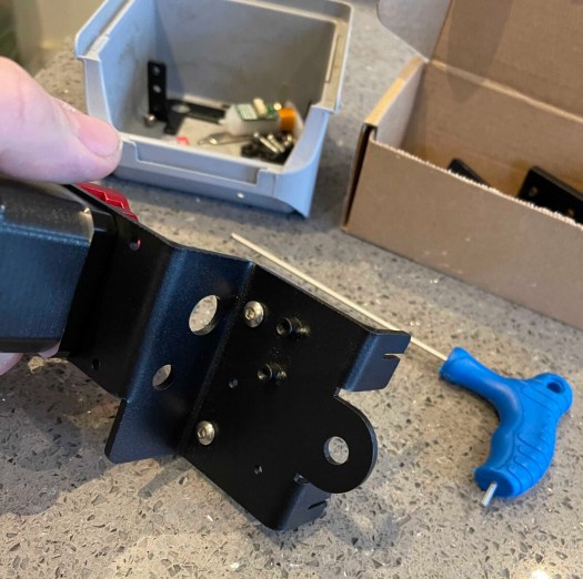
I know it’s a little late but been ruff Christmas for my family. back now with more fun projects going to add to my modular shelve as my secret Santa came through with the bits, I asked for. part five of mods I being slimmed back as i am missing parts from china will add them as they arrive in part 6. that’s if part 5 all tests work well. as having an issue with part 4 that requires fixing. looks like a bad solder joint. on the aviation plug so made a jig to help solder it.
I am also considering making all in one jobs using a remixed version of designs on Thingiverse but working it all out now.
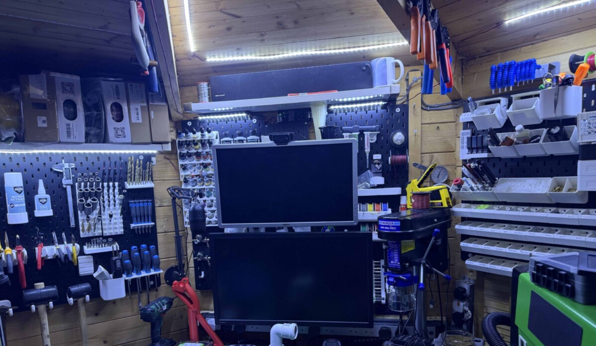
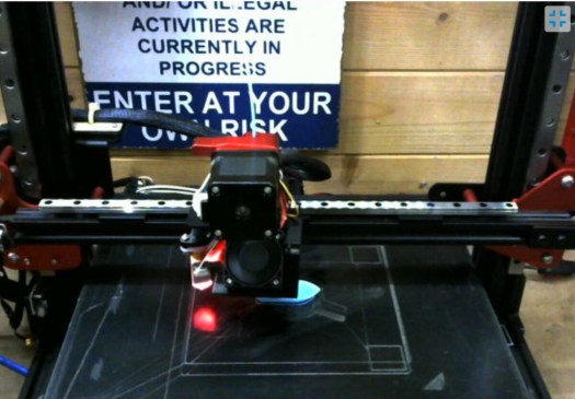
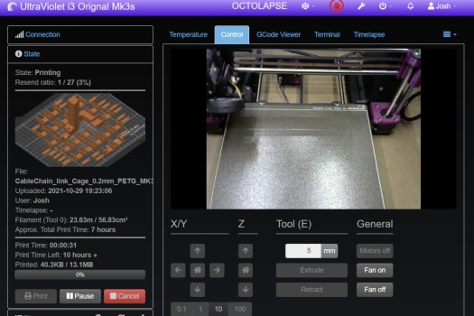
sneak preview of how the printer is looking atm. more to follow when amazon deliver missing parts today
so like all my ideas I am sitting in the workshop looking at how to reorganise my paints and small wiring loom’s. So I have a little wall space left and my model paint collection taking up 3 draws on my dump bin wall. so howto free some space.
so out with callipers and measure up some bits bottle dimensions and then over to light burn and make a quick sketch before I export it over to fusion why light burn I don’t have a copy of AutoCAD anymore I don’t have the finance to get one. the sketch is in 2d as you can see below after its imported dxf file into fusion 360.
From 2d to 3d is just a simple job of extruding parts so the base if -5mm then the part holder is +10mm then I add +20mm, paint holders with wire holder I have created a c pattern I extruded the whole thing +60m then find the centre point for the hole and insert cutout 20mm as I know my pipe I’m going to use..
I then added 5mm wall mounting holes to the centre point of the horizontal and jobs a good one still need to design a spool holder for wiring but that’s a 20mm tube I have kicking around.
ready for print test
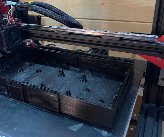
away we go in petg for the 17ml bottles holder shelf.
airbrush paint holder is done very happy with it.
empty
filled works perfectly
I will try the wire spool holder next as already have some spool ends for the 20mm pipe I’m using just going to test it fits the spool before I commit to print. also added holes for the wire to poke through and be ready for print. the 20mm fits like a glove.
20mm pipe fits perfectly.
Right after the success of my airbrush paint holder going to print with wire holder time to try my mini wire spools
fingers crossed no supports.
overnight parts and came out perfectly have cut down some 20mm duct pipe to fit.
I am going to quickly design some spacers for the spools and remix some end caps for the project as the concept works just will make it easier to assemble it’s looking good so far
test fitted and all fits got make some spacers.
the printer is busy doing the 200ml bottle shelf so afterwards will run the spacers and put it all together.
Spacers and ends i have put together.
The bottle shelf works well too so will put all 3 designs up on Thingiverse later
Perfect fit
works well on the wall
quickly builing more as i find more paint and dye.
might add a new design for resin dye as draw full of that as well to store
now to test spacer washers for the wire see if that works need to print 2 more shelves I will do this overnight I think. first, some tweaks Right inner spacers need to be fatter going to test 2mm in width but that’s the only improvement I think I need to make.
new 2mm spacers fitted ready to find some wall space. printed a second one for the rest of my wire
Much better fit with bigger spacers.
So the modular shelves are born. I am sure i will be adding to the collection as hoping my secret sainter has come through as have two nail polish remover bottles coming my way. well as apparently they are good for isopropanol alcohol and nail varnish remover dispensing as i use loads on cleaning things and a better way to waste less. so can see an added design or more as I find new ways to space save in the workshop..
A fun days project
You can find the design up on thingivers. will do a video of me playing around with fusion 360 as a lot of it is experimental as I was taught in 2d and still learning 3d and CNC just finding the time to have a day playing with family and day jobs sometimes is hard. but i love it.
So this is all going to be 3d printed mods I have already done a 35hr print on the control board side I have printed the new feet need to print the SSR module clip might set that up whilst I am remote in wales the joys of being connected. so all I will need to do is 2 lids then will be ready for the pro upgrade.
also mounting on the screen on the side of the machine. might need to reprint the printing bracket. as want it on the left-hand side of the machine.
23hrs of printing done should be finished by the end of the day,
so just uploaded it to the local computer and now have kicked off the amazingly long 23min print haha so will only be 2 x 7hr prints left when I get home on Monday. just as I feared the small print it failed never mind noticed and cancelled the print. will check back with the main print later.
80hrs combined printing still a little cleaning to be done
wow, that’s the long prints done now for some smaller prints and armed with elnet the king of hair spray when it comes to getting prints to stick well. as Pritt stick is too messy. wow just saw the bend in the heat bed how did that happen bent it flat again. just going to adust the bed by probe till it’s nearly on the money then I might lock tight them in position for the moment. probably should have done that before I kicked off an 8hr print.
5 layers of 95 done
I will be going over to a flexible steel bed soon but till then I am going to continue on the old fashion way well till the credit card bill rolls and I then have my monthly spending pot.
so smooth a 4hrs to go.
think its dialed in now.
starting to get ready for build
lids and SSR printed and that just under 1kg of filament was done. on the case.
All parts printed for pro conversion
last time it will look like this
so time to strip out the old box and fit the electronics in the new one oh and to add the new feet so it will fit.
just need to order some silent fans as the control box fan is really annoyingly loud so I have orderd 120mm nocturia fan and I think i will need to order 80mm one for the PSU supply. I will be opening that up in the rebuild as one i dont know its voltage and 2 pin numbers 2 or 3 so will order that when i konw.. I then have to think about speed control as i don’t think they need 100% speed but that I will be looking into as we go, as going to monitor temprature with a probe in the electronics low voltage box.
Have been thinking about a name for my cr-10 modified machine that came up with cave monster. so the next round of modifications to the code will include a name change haha. will attempt to design him a logo as well for the boot screen.
as i have been spending alot of time getting everything printed for the next step i have been customising my octoprint layout and feel. also on christmas crafting for friends and family so yes been a fun week that and i am re jigging the work shop as need to add storage for extra tools as need to make it all work.
High voltage side.
time to look at power supply and lable up wring before i strip it out the box. next up power input and switch. I will be making new wiring for all power elements. First up adding the mains power plug and switch. looks like the are going to need a little help fitting so out with the dremal and they now fit. as it cold have stopped halfway through the job as working how and where to route the wiring and fit the ssr to the psu.
Heat Bed mains and switch in
now to figure out this mess
all high voltage done.
Also, going to wire the printer PSU through a 5v relay so i can turn the printer on and off through the raspberry pi cover this in the Low voltage side of the board but will cover that later.
Low voltatge side.
Now i have the power run across the board I will either add the bucks converter to step the 12v down to 5v to run the raspberry pi or I will use a mains adapter this will allow me to shut down the printer where as the other way would be a total power off. whilst I think I will install the pi and the main control board. am then going to install 2-way relay board so i can switch on/off the machine and lights via the relay.
boards in ready for wires
final image for refrence.
need to think about this as big arse fan wil be above this.
Might run the wiring under the main board to keep it away or i mgiht just exstend the wiring.
Time to connect all the power wires and the heater wiring to the board and the SSR.
Now to add all the board inputs and output so end stops motors and sensor
next, it is time to fit the 120mm fan to keep things cool as its a 4 pin I will only use the 12v supply as should work will test this theory later also waiting on t-nuts so I can bolt this to the frame should have them later on today so will finish wiring ready to bolt it all together.
got one more print to go on as adding halo light to the camera so I can film all the loverly creations that I am making with the printer but that will be done once I have installed the rest of the electronics. going to make the camera mount a little more sensible as i feared there’s a little bit of a wobble when running.
testing halo /focus mount is not 100% right but fits and works soldered some longer wiring i will be
As I am waiting on parts as amazon let me down I will be getting the last bits sorted ready to bolt the boxes to the bottom of the printer. ok been a week had a family issue that’s now come to a sad conclusion. so back in London will try wrapping this stage up by Xmas but see what happens.
How my plans have changed
its been 2 weeks of hell over Xmas father in law passed away suddenly so was in wales for a week then came back to london and wife and son both have covid so stuck in london in the house i am negtive and they are both ok.
bad new but good news been working on the project and ironing out my kinks with it so where to start
It dont fit under my printer bed like its ment to due to my custom bed so instead of having a hissy fit throw 70 hrs printing. I am going to let be and will figure it out as i go i have welded the 2 sides together with some high strength glue and exsellitator now bonded together
custom mounts piot holes drilled.
now to screw it in place.
stand offs in and board scured.
relays all wired up.
New power for lights and speed conroller wired up.
All in working
i then have added some custom stand offs for the fan speed controler and 2 channel relay. i then drilled holes for external raspberry pi power and for fan controler knob. oh and power connector for the halo.
bit of wiring changes to the printer can be powerd off and on by the raspberry pi also using the 12v psu to power the halo light as well also had to change the wiring.
and we are good to go i am waiting on the next mods to show up from the far east got one PCB board still to fit so before i bolt it back together and start testing the new fetures
ready for install just power headers for the pi and add USB PCB when it gets here.
I will leave this here. get ready to part 5 this will be the final part i hope. so whats coming well a UPS 12v board from big tree tech. New fexable bed for the machine and fliminet runout sensor from big tree tech and upgraded linier rail upgrade and thats it.
Well as I await parts I will be working on a few issues and also designing some parts.
What I did not mention in the last part is I managed to drop the control box moving the printer back into the cave as it’s so big and the doorway is so tight. it is back in the cave no so I need to do a strip down and see what’s making my Y-axis go in reverse.
I have a feeling it’s damaged cable or end stop both are on order so should start on this shortly as really thought I had come to the end of the update journey. But no it’s become a paperweight well hopefully not for much longer.
So in part 3 plan is as follow.
Fix reversed Y-Axis after drop
Time to invstigate whilst i wait for new bracket
Fit proper X-axis linear rail bracket.
Reinstall hotend with direct drive & Install new hotend part cooler mod
Print a camera mount:
Fixing the reversed Y-axis:
this was working right till the control box that was balancing on the bed fell off and dangled. now the printer when homing goes in reverse. very odd I have ordered a new wiring loom and end switch. going to start by swapping the bent up end stop. that main pull was on and replace y loom fingers crossed. The end stop has arrived going to fit it now and see if that fixes the issues. If not back to waiting for the loom.
Looms arrived was the Y-Axis end stop wiring has broken out with the old in with the new.
Installing the updated motor mount and bed upgrade:
After ruling that wouldn’t fit the mods and I didn’t think they would fit.
I changed my mind and thought what’s the worst that could happen? So have fitted both the bed wasn’t too bad once I had lined up the centrical nuts up. I then added the new motor mount this wasn’t as much fun, as mounting it needed some parts that were not included. fist up need M5 T-Nuts luckily I had some, countersunk m5 screws again luckily I had these. right now to reattach the Y-Belt to the motor and the bed. for F#&k sake the belt is 100mm too short. looked through my draw of printer parts and spotted gt2 belts was a loop cut i and then rethreaded the bed. ok no to reattaching the end stop it wouldn’t fit as the holes in the bracket are for the raw small micro switch so have mounted the original end stop back in place if this causes issues can modify the end stop to fit on the brackets with old bent up microswitch scavenged for bits let us see hopefully not but have a backup plan.
all back together and homes ok so now for the next part of the project.
Time to invstigate whilst i wait for new bracket:
Now that I have a working printer going to do some more testing to see why it’s not printing right.
ski jump did hit camera mount im testing for later. bars hav foiled my install idea.
right has put a spirit level and my z was out slightly so have adjusted one of the rods. and the new result is better but still off. Hoping on the bracket to sort this out a bit better.
Just waiting on the arrival of the X-Axis bracket now as I am sure there that that is also compounding this. So as you might have figured I am doing other bits whilst I wait and updating this post as I go. Hoping by the end this will be an awesome printer.
The bracket is in the UK just waiting on delivery so probably in 48hrs time. so time to strip off The offending bracket and strip down the hot end ready for the new bracket to arrive
Fit proper X-axis linear rail bracket.
Out with the v2 bracket as there’s a 5mm difference between the centres. as you can see I have removed the modified direct drive hot end as I think this is also the issue with print being fine on one side and in the bed on the other. time to add the bracket and fit the 2 screws. before moving on to the hot end and direct drive. it fits but!! mgn9 rails kit not 12 argh never mind ordered new rail so will sort this out next week.
braket fits yes
so happy
old modifed one
Reinstall hotend with direct drive & Install new hotend part cooler mod.
I have repopulated the direct-drive motor I have rotated the motor for cleaner wire management. I will now reattach the hot end and fit the modified parts and hot end cooler as it uses existing fans and screws. I had to get my craft knife on it to make it fit but fits fine
right time to reasemble.
all re attached
bl touch re fitted now to measure off set
I have reattached the BL Touch need to measure the offset form probe to the sensor in the x-axis its -41 and in the y axis, it – 5 so will need to recompile merlin to get it working to make a note of the setting for later. I am already going to need to do this when I add other functions to the board that i will cover in the next post,
Ok next issue
just did a test moving the extruder head to make sure it homes ok and there is a bolt head hitting the z-axis bracket so I have solved this by swapping it for a button head bolt that now makes contact with the end stop so homes fine.
Right, let’s run a bed visualizer scan and see how it is now.
about a mm diffrence across the bed
So out with the solid mounts and I think i will be adding back the springs if i can find them if not will order a set and go back to configuring it manualy.
So back to my box labled printer parts to see what i can find as i have a feeling i saved my springs. YES I did saveI them so will fit them going to to look for some nylock adjustment wheels on thingivers so i can lock them in possition
me being me put the springs back in and spent a hour getting bed as flat as i could before i set saving the mesh and dong the z offset.
Much better
Time to print a camera mount:
I am using a c270 Logitec camera as I do on all my printers as nice and cheap. doh printed the wrong parts need to find another fixing bracket as printed vertical mount instead of horizontal one never mind. Just a few more hours and then will cannibalise a second-hand c270 that I have ordered so inserted about £24 on amazon and got it for £13.
I have used this one before and it worked well so I pre-printed this design that can be found here. All you will need is some m4 nuts bolts and 4 t-nuts is fixed to the framework like so.
not good view
too short
might work
ok, it’s probably going to vibrate like a bitch but I’m game for a laugh lol.
view from the camera lol
Right now up to date with all mods, there are more to come but going to make sure I have a functioning printer before I go splash out on any more parts.
Calibrate and do some calibration prints without issue,
Now that all is working let’s start to play with calibrating the machine and getting it all working right. so first up is a bed levelling program not sure if I need to run this at the start of the print each time. can make it fewer touchpoints and then to calibrate z offset height.
Still needs a bit of a tweak I think will do a few more adjustments to the springs to get it just a slight bit more level as seems beds off a slight bit. I now remember the pain of manual bed levelling but hope it will be worth it.
made some firmware tweaks let see if this fixes the machine. getting there nearly dialled in just got to drop the head a few 0.01s and we should be good for a benchy test.
All sliced up ready to print think that will be tomorrow
Success i have a printed bentchy will be looking at it properly when i get home later.
checked in 20 mins after start
then this monring so it works
so got home had had 1 layer shift so have tightened up the belt and run the print again. now yay had a filament jam and a tangle that made the print fail halfway through so I have decided to 1 make a better spool holder for the printer and 2 go back to sold standoffs or silicon ones so some play but can be locked in a level position.
so whilst I wait for parts again printing spool holder.
Now to glue and fix it to the wall.
It all looks like a good time to print something bigger before I try doing 1 day 12hr prints on it.
eureka is all working well now to do some calibration prints to make sure all is well in 3d printing land.
so after 5 calibration cubes and a benchy or 2 or 3, I think I am nearly bang on as level as I will get it with a bl touch across the bed.
Layer shift tangeld spool
a part from that looks good
New Spool holder installed
Away we go
4 cubes later
time for a final go with black
Conclusion to part 3
Now that I have a working machine I am going to turn it into a pro by losing the control box.
don’t worry this will be part 4 as having a working printer that’s improved the prints and has improved the quite ness of the machine, not the control box but that will be part 4.
but back to the big print
well, about 2 hrs in and it’s printed 2 layers a little bit of stringing but let’s see going to risk leaving it alone for 2 hr or more. ok came back 6hrs later and yes it’s still working I am amazed my self oh well 1 day 3 hrs left on the print.
looking good
Morning all well been printing for 23 hrs now and still going a strong slight bit of warping not bad and won’t affect the massive print this is side 1 of 2. Apparently, 23 hrs to go but it’s 61% complete so I think it will be less.
Happy the machine is working right so will show the finished side a put a pin in part 3 get ready for part 4 more modifications coming up going to order Y linear rail upgrade so we can start speed testing.
35hrs 10 mins and she is done this is pcb side low voltage.
right, this is the end of part 3 as 35 hr print is complete and looks great. did thteh enw feet over night and now doing the rigth hand side so another 35hr print.
then wehen i get back from wales i will print the lids, and start adding the electronics.
but thats going to be part 4 over all its working well so let see how we go now 1% in to next large print.
Part 4 will be all the 3d printed parts and part 5 is going to be the linear rail conversion on the y-axis.
so where we left off printer moved home and levelled then failed so in this exciting chapter going to strip out the control box and add a new brain to the system.
so as I am upgrading the brain I might as well do some more mods so a colour touch screen is included in the kit. so will be adding that as well. I have been watching a few videos on compiling merlin. so have downloaded the nightly bug fix and will talk through compiling later on.
so time to jump back in there. as I have one working printer at the moment I am going to start off with printing the new screen holder as going to lose the control box completely. these things take up space.
so over to Thingiverse and found this Slim and Elegant BTT TFT35 E3 V3 dual-mode touch screen Extrusion Mount see the link here.
Over to Prusa slicer sliced and uploaded to ultraviolet. as neon orange is offline.
away we go will check back in 9hrs time
2hrs 45 mins into 9 hr print
9 hrs later one screen adapter is done
All done
All cleaned up
some M3 screws later and it’s ready to wire lol ok I forgot to take the screen protector off never mind let’s get it all working first.
it fits
stand offs fit
all lines up
spot the reset button
all screwed together time for some wires.
one part is ready to install some m4 bolts and t-nuts and will fit onto the frame.
I will print the pro enclosure once I have the printer working online as the cr-10 is the only printer big enough to print it. will print all small parts whilst I get the cr-10 working.
have tried the y motor mount and dont fit right so abandoning this upgrade for the time being. now to do some compiling
Compiling merlin for the first time.
This is sort of new for me as in have flashed my old original cr-10 board before using Arduino ISP programmer and source code. but now it’s all moved over to the Microsoft VScode environment so much easier to do. as the cr-10 has a pre-built config file it’s for the new SKR E3 mini v2.0 BigTreeTech mainboard that’s repacing the stock board.
so you are going to first up need to install VSCode / PlatformIO programming environment. there are plenty of guides on this. once done you will need to head over to https://marlinfw.org/meta/download/ and grab the latest bugfix file you will then find a link in the config folder for the example zip this houses the configuration.h and configration.adv.h files and boot screen files you will need to drag these into the marlin main folder.
open the project in vs code.
in my case I am installing bl touch so needed to change settings to include bltouch and safe z home, also added about probe offset and a handful of other bit. There are vidoes on this so i wont try explaning it all.
I then selected my board type in the core settings. and built it. after the compile was done I found location firmware.bin and copied it to sd card to flash the mainboard. you will need to power on the machine and it should all be ready with the new firmware. will test this along with the new screen shortly same applies for that can be custom-built or you can just use stock firmware.
Now whilst doing my research for this project. I saw the filament run-out sensor porton the new screen so going to use my filament sensor from my old ezout board as it’s compatible.
I am also going to use neopixle function as well so have ordered 1m of led tape. will be experimenting with this soon as I will need to recompile the firmware to use the function actualy will turn it on now and play later time to do some more reserch as wont complie needs some addtional settings will do them first before first switch on as then when i assemble the board i will be able to playwith it will runn cable ready for it so all in place for when the tape arrives
I am also going to name the machine so i know its talke the frimware before i start testing.
now to upgrade the components.
So out with the old in with the new:
so toime to take the old board out
wiring all swapped over wiring to the new board so that it’s ready for its new firmware. whilst I’m doing this have also fitted the final part of the last lot of upgrades to the machine. new motor bracket fitted.
time to swap over part
halfway done
all swapped over
Time to switch it all on
Time for the initial turn on with new screen fitted in enclosure hole as till I have finished off the new mounting box for the machine won’t mount it till then.
turns on lights up and turns off ok a little bit of googling figured out the issue because i have bltouch wiring plugged incorrectly.
now I can see I have messed up the screen with an improper firmware update. long and short of it don’t copy the update to the sd folder to the TFT screen.
Dont copy over the file saying copy to sd.
only copy theme folder content TFT model number and config.ini and just like that is fixed now to flash the firmware I have compiled with fully bltouch customise on. all done did have a message that bed mesh couldn’t be found but after running bed levelling got a saved to eprom message and that’s resolved that.
its alive ready to do offset and test.
wow, it’s so quiet moving around the printer all I can hear is the noisy control box on my list of things to modify.
Ready to print have done my z offset wish me luck.
nozzles hit temp beds not heating up time to check connections. brb. ok after checking all connectors and solder joints i have done over the years was poles on the SSR some how got switched now heating like a champ.
My first print failed as need to watch a video how to do z offset done right as was about 4mm off the plate but on a realy grate side it works it runs were its ment to. so very happy. watched a video all of the menus have changed but i think i have got it just going to start a test print before i move the machine back to the man cave.
bed seamms very off not sure if its down to my bracket modification.going to look for the bracket set only as then will save money on getting this sorted time for a evening of reserch fingers crossed i can solve this i am going to put this down to my mod of the braket
So have found braket correct x axis braket and orderd it and a new braket 10 to 15 days i will hopfuly be finishing this project. as i am waiting for parts i will do some other mods then leve part 2 here and come back with part 3 when the parts arrive.
Time to print some Upgrades whilst i am waiting on parts
As my wirings got heavier going to print a drag chain to sort that out so overnight parts on the Prusa will report back in the monring.
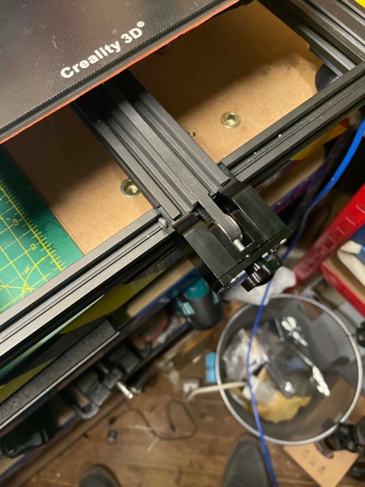
all done ready to fit. had a near miss with 2 clips shakeing loose. but it servived the nite.
lets see if it works.
all printed
It sort of works but is a little weak for my likeing i am going design my own chain holders for the liniear ralil mount and were the old exstruder motor used to be to use with some stock chain. got to free spome space up from my drive as fusion isnt working,
Hot end part cooler
been looking over thingivers for other mods i can install on my machine as you know me with this ever elvolving project. so as i have direct drive installed i am limeted with hot end cooling mods as i know the stock one is less than great so i have found one that i think will fit so time for another 7hr print. going with the AJS hero v2s as it has bl touch mount and uses factory stock screws so should fit.
will check back in 7hrs
morning time and all cleaneed up very well will be stripping offending bracket later in the week from the machine and install new one wilst i wait for x-axis braket that is alreay shipped from china.
test fit with new braket and have removed 5mm off the top corner with a dremal saw bit. Now a nice snug fit with out interfering with the bracket or hotend.
just got a ghost trap to build for the boy before i get on to stripping down the hote end and removing it ready for the new liniear rails bracket that is shipped already so 10 to 15 days time the project will resume.
Will it improve its printing ability? or will it be an expensive mistake?
This project is going to kill or make my CR10 v1. The story so far :
2017 Received the machine from Aliexpress Creality store.
IT worked out the box did some big prints suffered from ringing kept vibrating off level suffered form glitches and so the story begins
brought the duel z modification less ringing started to get the hump with the board shaking the leaving screws lose. so decided to get the EZABL prob kit brought it got it all set up worked great had a major meltdown and destroyed itself with mass blob filament could not unclog it so I brought a complete extruder. took months to arrive. I disassembled the machine and put it in the attic.
meanwhile, I kept on using the Prusa mk2 that I keep on upgrading to the latest spec so forgot about the cr10.
Lockdown happened health workers needed PPE to save lives I joined a group of people making ppe. I started my print farm going 2 Prusa around the clock pumped out face masks ruffly printing 25 masks a day. but wanted to help more
brainwave I got that cr10 in the attic I can fix it as now 100 times more confident with repairing machines. So fixed the cr10 added silicon bed heater with SSR 1 good print out of my machine then for some reason the bed temp was reading very high in the 800c back in the attic went for another year have moved all business servers in the house so needed the space back so brought the cr 10 back down and put it in the workshop,
since then I have sworn at it a lot as keep tripping over and finally decided enough was enough swapped thermistor as thought that was the issue. it was but wasn’t, I finally figured out that it was the gunked connector in the control box that was that actual issue. fixed it after soldering a new connector into the plug on the box.
After a binge on Ali express and some more local parts, I’m going to modify the F#%k out of it and hopefully not go down in flames.
Let’s get this done.
I am going to lose the EZabl probe as has intermittent issues and the upgrade to a BL touch will mean that the EZout is no longer needed.
So thanks to the 3dprintingkid. I have been armed with a brand new ender pro 1.1.4 mainboard which I will be flashing with the BL Touch upgrade kit and latest Creality firmware. It’s already been flashed with a merlin 2.0x but going to go with the Crealitys version for the time being to see how it performs. if not will make my own compiled version.
So I will then have hopefully reliable levelling probe. next, I will be losing the Boden tube extruder for a direct dual drive upgrade off amazon with some belt tensioners being installed and proper z-axis motor mounts aluminium. I am going to upgrade the 8mm rods with some proper anti-backlash nuts.
Then it will give it a test whilst I wait for the next batch of upgrades to arrive from china within 10 days according to aliexpress.
So we are going to get a custom bed chassis, with an Upgraded Y-axis motor bracket.
then I will upgrade X-axis and Z-axis with a linear rails upgrade kit.
Finally, on to the frame, I will fit a stiffening kit and adjustable z rod holders with bearings.
Well, that’s the modification of the parts done. if they all work will be time to do some 3d printed upgrades.
Time to start.
Time to strip the machine down and swap out the old mainboard ready for the flash update. so first of all I have swapped over the cables and connectors from one board to another.
Cables swapped
New board in
now to remove the old board from the machine. now to bolt the new board in the machine.
Off with old EZABL
Time to remove the ideler
Making a collection of parts off the machine.
Time to remove the extruder
Extruder motor gone.
Exstruder removed
I will also loosen the y and x-axis belts and remove idlers ready for new ones. then will remove the extruder and extruder motor and PETG tubing. So I will be ready for the parts to arrive tomorrow.
A new day and a bit of a build ahead well once Amazon has delivered.
Got the first batch of updates,
Going to be a fun night
First up going to replace Y-axis tensioner with nice solid construction easy to fit.
Fitted and tenctioned
Solid construct
next up time to install the new extruder drirect drive kit.
Ajusted and fitted the new direct drive
Had to remove 5mm off the capricon pteg tube.
Exstruder now filts and can be screw down.
Time to fit the cover and Braket
BL touch Bracet installed just need to fit the sensor.
Time to install the wiring.
Right next up to add the X-axis tensioner again solid construction the supplied screws are too long luckily had some M4 x 10mm screws kicking around nice snug fit.
Going to change the motor mounts as they are easier to fit 4 screws each and done much neater.
Old motor mount
New motor mount and anit backlash
I installed a clone bltouch that didn’t work very well have been waiting on parts to continue the project. kept on crashing into the bed so ordered the official one from Creality
a week on and have most of the upgrades so now time to fit them all first up going to do the x-axis with linear rails. you can find the kit here have to take off my newly installed extruder and add the new rails.
Exstruder stripped off
time to add the brakets
now to add the rail.
now to refit the extruder
That was very easy to do next up is the bracket on the extruder. it doesn’t fit what the F%&k I ordered the cr-10 v2 must have a different head on it. time to modify and make it work! if not will have to bite the bullet and order the correct one so out with my needle files and time to lengthen the hole. well 30 mins later now fits. but then the probe mounts don’t fit right. ok solved that put the bracket on first then nudged it over then the cover fits so looks like it will work I am now going to wire the official BL touch kit. won’t fit it yet as need to remove the x gantry to fit the z linear kit.
lets strip everything off to fit the braket
all ready
it dont fing fit argh
finger file to the modify the part
fits perfectly now
and i think its straight.
all back together ready for bltouch
the one thing I will say about fitting all these parts is there are no instructions just wish that aliexpress manufactures would think about this as would make life easier for us end users.
time to strip down the z-axis and liberate it from the machine then to install the left and right z rail all fitted and now to rebuild x-axis with new brackets. the machine is starting to come together just need to fit the extruder.
had to rotate x motor to get it to fit with the bracket supplied. next up I fitted some side struts for rigidity lets see if they help. can find the struts kit here
all done ready for the extruder.
I just need to fit the BL touch and then do some cable management.
nice offical kit.
all fited
cable managment sorted
had to find screws as non provided for the exstruder
all done ready to flash.
ok now to flash the firmware with Creality ISPprog.exe all done time test. lets do a auto home. argh, mods not allowing me to hit the end stop time for some mods some m3 nuts will act as spacers for the motor mount now works, as with any project some times just need to think out of the box.
time to flash the system
Right auto home x and y hitting wait a moment I have no z oh I see flashed it with standard merlin. Reflashed and all works had some binding issues with z that I have fixed by adjusting the threaded rod screws and my trust spirit level.
Now to offset z so we can start to test what the mods have done for this machine and will I be doing further mods let see quite nervous about the first print.
final bits to install z rod ends are now installed.
time to find a sheet of paper and see if my machine calibrates ok fingers crossed.
away we go auto home done over to Prepare menu then » Move Axis » Move Z now to lower the z till it grabs the paper and then make note of the amount and then go over to
In my case it’s -01.50 go up to the main menu then go Control » Motion » Z Offset enters —01.50 time to store the offset.
go back to the Control menu, then select Store Settings. The job is done now to test print
Failure of the bog-standard Creality firmware 1.60 has issues I think the printer is heating auto homing then going through the bed levelling part then it starts to extrude and rocks backwards and forward on the front of the bed. hmmm
F@@K it 8bit Creality board can go do one time to spend some money as I said going to throw upgrades at the printer till it works right.
Have ordered bigtreetech skr mini e3 v2 with TFT screen so will be compiling my own version of marlin for my 32bit board.
I think I will also swap to linear rails kit for Y-axis I might just sell on the custom bed as the kit comes with all the parts including the bed.
so I am going to end this here till I have the new mainboard and can make some progress.
Ok, what’s so hard about adding a keyboard drawn to a desk well if my desk was solid wood would not be a be an issue but seeing as I cannot afford a nice metal or wooden workbench I have gone down the 1200 x 600 racking route. and have had to balance my keyboard on shelves under the desk no so easy when the bench is full.
The Idea
had been bugging me this for some time I was going to make my own draw using some wood and draw runners. but then was thinking back to my days in IT when we had a massive server cabinet with keyboard draws. so straight on to amazon. found 3 or 4 possibles but none had the right mounts or size for the keyboard I am using.
I then found laptop draws and that was the answer to my issues. prime delivery next day now to make this fit. been running ideas in my head since yesterday on how to fit it as fits the 50mm gap I have created.
The Draw
Fits very nicly
What it will look like
The plan
I am going to cut down 1.8 meters 50×47 mm wood into 600mm lengths 3 of them.
I will then measure and drill holes fro draw mounting points through the wood I will countersink them so I can add bolts flat to lengths will then blot them to the 2 lengths.
the 3rd length I will use to strengthen up the end of the bench will be making a quick release for the table saw, pillar drill and sander. more on that in another project.
I will now measure up the tabletop and drill 3 holes and countersink them into the tabletop will then screw down the tabletop after that is complete I plan to use carpet tape to hold down the cutting mat. well that’s the plan wish me luck
The build
Monday Night:
Hand saw out 3 legs cut. time to test fit them. ok, Need to take 5 mm off each length as slightly too long going to notch out the top and bottom so it fits in the frame. Have one done works just need to set up the piller drill as want my holes to be true then will test fit
One in 2 to cut and notch
giong to add a usb hub to the back of tray
Noctchs done fits nice and leval
I want them sitting nicely in the frame as screws from above will clamp them down onto the tabletop. hold on now waiting on bolts as I could not find any locally so amazon delivery tomorrow. will notch other 2 lenghts tommorow.
Tuesday Night:
Time to replicate the frist length 2 more times and fit every one more time before i put the top back on.
1 done 2 to go
Time for a scketch for idea
All leval and notched
Now to measure drill and countersink. fits like a glove now drill the tabletop. on a roll now to stick cutting mat down as this project done.
this was a workhorse for a few weeks then it drove me mad I treated her to an upgrade worked for 5 mins and threw its toys out of the pram.
brought it back from the attic as needed the space for a server so for 6 months it’s been kicking around the floor of the man cave or I keep stepping on it.
so today is the day I either fix it or it goes to wales as times run out for my cr-10 I only want working equipment in my cave as space is tight.
So what’s wrong with it well had something fail on the heat bed as it’s spiking the temp to 800c it’s not 800c is 25 max and the printer won’t work.
now have replaced the MB(motherboard) with a newer one then flashed the latest firmware. so it’s time to dig further. I purchased some cheap thermistors from my mate ammy (amazon) who don’t get my wife’s humour.
Time to start took old thermistor off the silicon heat bed, I will silicon new one in place if this fixes it I spliced the wiring from old to a new one I then soldered it in place switched on the control box registering 730c hmmm so came indoors and took the control box ti bits and plugged thermostat directly in the motherboard and powered up all is fine. so going to wire up a new wire from the heat bed to the aviation plug.
fingers crossed as will then modify my machine some more as it’s time to make big prints again. will figure out the updates shortly. once I have done a test print need to order 1 part that will be with me today.
So soldered back to the plug and 730c again think I am going to check the control board to plug the connection. been thought my notes pin 1 and 2 are definitely the thermistor.
so it’s going to be from the control board to the aviation plug so time strips the box back will get to the bottom of this. have ordered 2 aviation plugs just in case.
duff plug or connection but as it has been gunked I have soldered in a new plug and put it all back together and it’s now working now to rebuild the printer.
On a side note, I have 8 upgrades so far I wanna try in my Aliexpress basket I wanna try so let’s hope I can fix this bad boy. as once working will hit the buy button and end of the month should make for a hell of a project or headache. A sneak preview of what’s on its way from China.
i
I will also look at some other mods for the control box as it’s big and bulky and takes up room in the and space is tight in the workshop. but more on that later.
When you know how to make 3d models and prototypes 3d printer is one of your biggest assets in the small workshop. this whole project took 4hrs 30mins to complete from idea to finished working design and 4hrs of this was the print time.
Back story
As I am currently waiting for virgin media to fix an issue with my router before I can make the new website live as need to port forward from the VR machine. So to make sure i can just start to work on projects I am re-laying out the workshop. I have had tools sticking out of dump bins as I didn’t have a space to place them it’s got a little out of control. so back to the problem at hand and the point of this post.
The issue
Bocsh Wireless glue gun never found a handy spot for it. so last night after pulling out my callipers for some ruff measurements. I decided to make a handy wall mount.
The MountDesign
So fired up fusion made a 40mm circle and extruded it to 55mm then added a new sketch and made a new circle 35mm at on end of the cylinder I then cut into the cylinder 30mm I then added a 5mm hole through the middle and then using a bevel tool made a cone to exit.
I then flipped the design on its side and made a 55mm x 30mm rectangle I then moved it from the central axis to the outer edge of the design and extruded it by 5mm I then added 2 countersunk holes. by using a circle tool and the bevel tool. Now to export it to print.
Now to drag it into Prusa slicer and slice away made this design so won’t require any supports of rafts to print. printed with 25% infill. gcode ready for upload to octoprint. Away we go overnight parts was a 4hr print left it going as having rigged up relays for the lights and power of my printers so once completed it will shut off.
The next morning– The result
As you can see worked flawlessly apart from me being overzealous with my talk driver screwing it to the wall. but it’s perfect for my requirement.
My next job is to add a keyboard draw to my workbench using the track system but need to go grab some bolts and 50mm x 50mm wood from the local hardware shop.
Wow, September already has lots going on back in London just doing a winter clean in the mancave. as has been come a bit of a junk pile as lots scrap around packaging and just too. tight on space. so I have been taking bits into storage or down to wales each time I drive down.
as want to do more with my CNC machine and get the print farm set up with my old cr-10 in the mix as well.
So changing configuration around in the shed. also having to rebuild my workshop computer as it died a death. I will be swapping over to the new site. just got to set up a host machine. get the new web server up and running. also going to redesign the site as was not 100% happy. so for the time will continue on here for time being.
But will be covering some repair blogs about fixing min temp on neon orange hoping it’ an easy fix do have a spare thermistor if worst-case scenario. I also think it’s time for octoprint rebuild and some cleaning of equipment and repositioning of the pi enclosures.
so long and short there will be some more content shortly. do that.
list of upcoming blogs
CR-10 can I fix this gremlin and get it printing the way I want as it’s been under my feet for a few months now. first up the heat bed going to replace the thermistor and see if that fixes the issue. if not will work will then upgrade the machine more to come on the mods later.
how to make workpieces jigs with a CNC machine. wife has been out buying gift ideas for Christmas so I want to be able to customise them with the laser. so going to design and cut a jig using a CNC machine. using fusion 360.
Making custom gifts with the laser and a bit of a walk around lightburn software. also going to get my rotary out and try some glass etching with the laser.


You must be logged in to post a comment.